139
Connecting to the Host’s RS-422A/485 Port
Section 5-2
1
14
13 25
NT31/NT31C side
Shielding wire
(25-pin type)
Abbreviation
FG
−
SD
RD
RS
CS
−
SG
−
TRM
RDB (+)
SDB (+)
−
−
−
SDA (−)
RDA (−)
−
−
RSB (+)
RSA (−)
−
Pin number
Connector
hood
1
2
3
4
5
6
7
8
9
10
11
12
13
14
15
16
−
23
24
25
RS-232C/
422A/485
connector
6
5
9
1
RS-422A
connector
Pin number
Connector
hood
1
2
3
4
5
6
7
8
9
Abbreviation
FG
SDA (−)
SDB (+)
−
−
−
RDA (−)
−
RDB (+)
−
(9-pin type)
PC (CPU) side
In order to avoid an FG ground loop, do not connect the functional ground of the
NT31/NT31C to the shielding of the RS-422A cable.
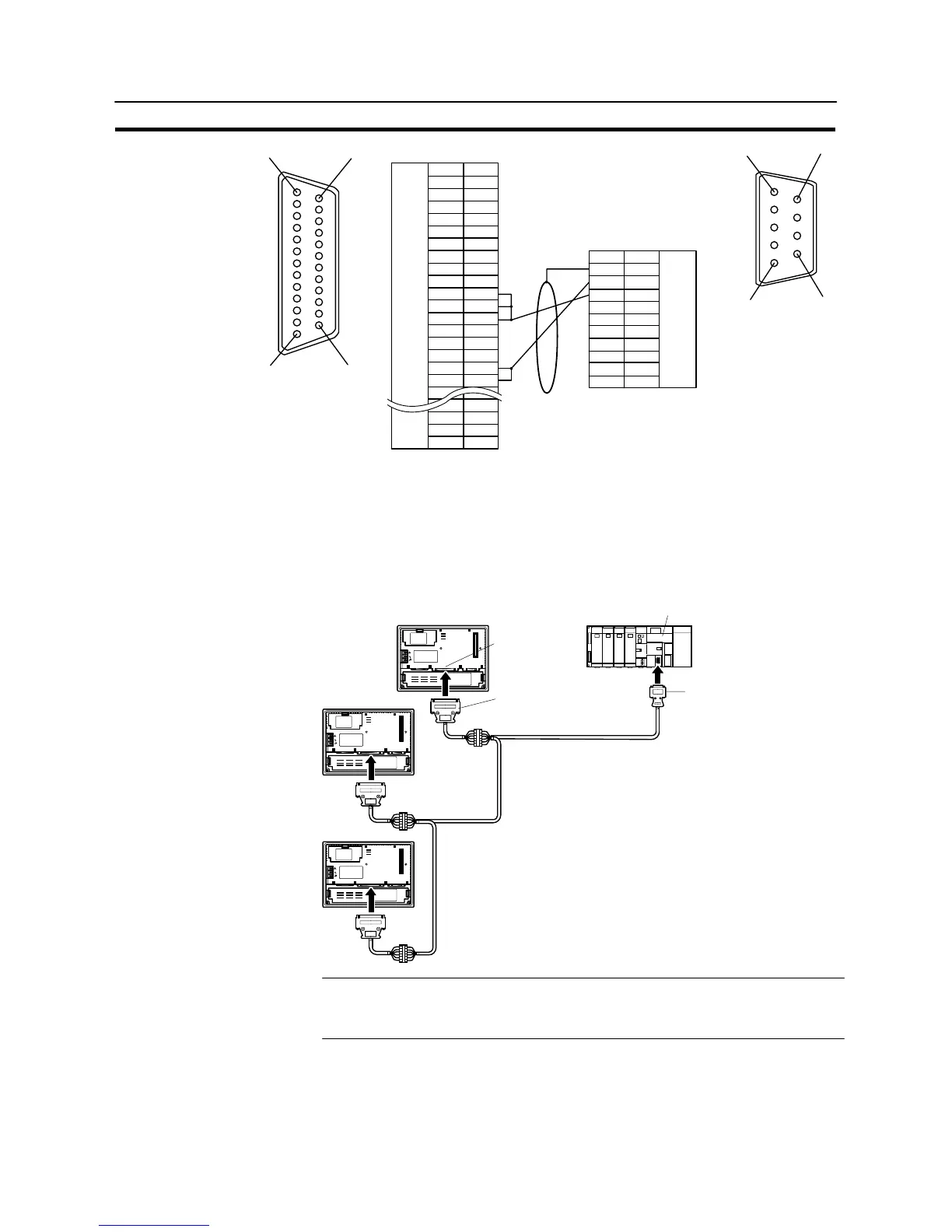
5-2-4 1:N Connection among RS-422A Ports
The connection method in which the RS-422A ports of multiple NT31/NT31Cs and
one host are connected in a 1:N connection is described here.
NT31/NT31C
25-pin connector
9-pin connector
Serial port B
(RS-422A, 25-pin type)
CPU
RS-422A cables
(max. total length 500 m)
C200HX/HG/HE(-ZE)
24V
DC
PRINTERPORT B
Max. 2 m
Relay terminal block
Reference: Communication using the RS-422A type NT link (1:N) method is possible when a
serial communication board is installed at CS1 series CS1G/H, and when a com-
munication board is installed at the C200HX/HG/HE (–ZE).