298
Memory Tables
Section 7-3
S Allocated bit
Bit memory tables can be allocated to the following host (PC) areas.
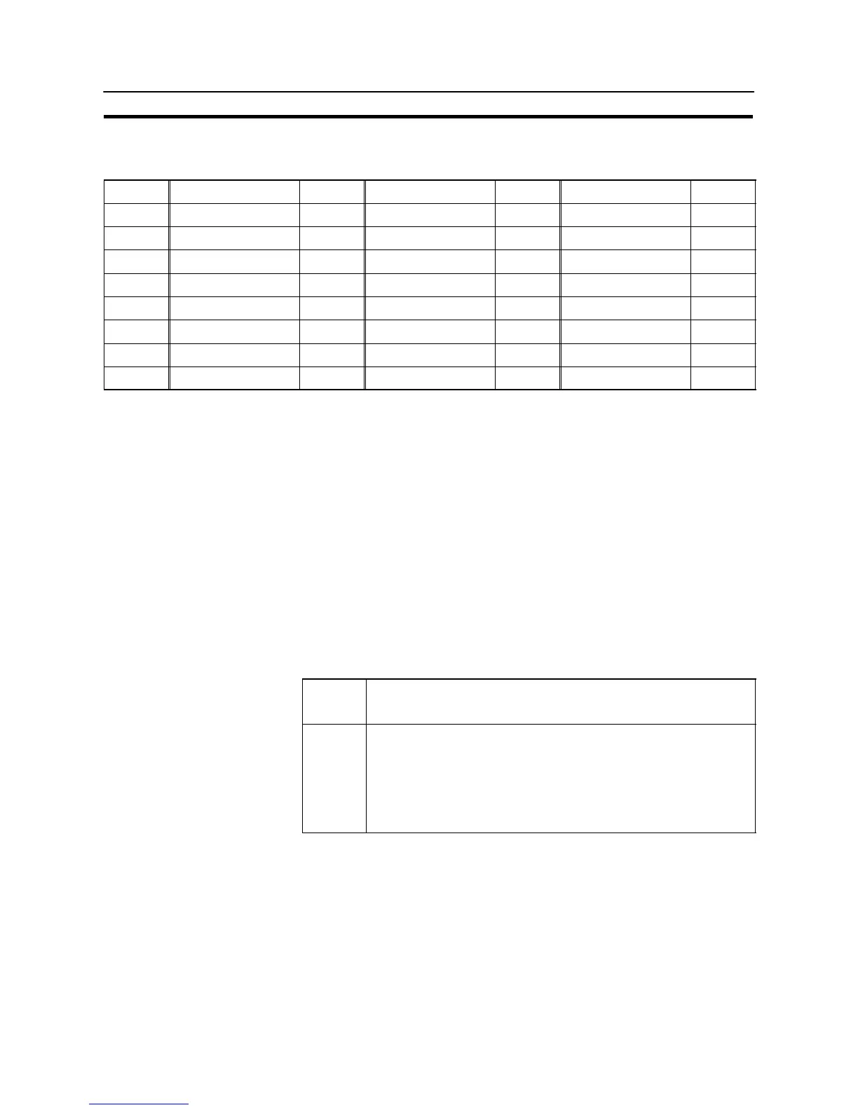
Symbol C Series PCs Allocation CVM1/CV Series PCs Allocation CS1 Series PCs Allocation
DM Data memory 3 Data memory 3 Data memory 3
CH I/O relay 3 I/O relay 3 I/O relay 3
TIM Timer present value Timer present value Timer present value
CNT Counter present value Counter present value Counter present value
HR Holding relay 3 – – Holding relay
AR Auxiliary relay 3 Special auxiliary relay Special auxiliary relay
LR Link relay 3 – – – –
EM EM Current Bank
*1
*2
3 EM Current Bank
*2
n EM Current Bank
*2
3
3: OK : NG n: Host link not available
*1 : EM (Extended data memory) of C series is available only with C200HX/HG/HE (–Z).
*2 : Only current bank can be allocated for EM (Extended data memory).
Since the special auxiliary relays of the CVM1/CV series PCs are all allocated to
system functions, they cannot be used for purposes other than system use.
The range of each memory area differs according to the PC type. Refer to AP-
PENDIX L “PC Memory Map”, page 684.
If the data memory (DM) is designated, a bit number (00 to 15) must be specified
after the word number.
[Display Functions]
S Screen changeover function
When using the screen changeover function, the following attribute must be set
in addition to the common attributes.
Possible Settings
Property
Meaning
Screen
Number
0001 to 3999: Screen numbers 1 to 3999
9001: Occurrence history screen
9002: Frequency history screen
9020: Screen for programming console function (expansion function)
9999: “Return to previous screen” designation
Number of screen displayed when bit memory table status changes to
“1” (ON)
- When a bit memory table is used with the screen changeover function, when
the status of the bit to which the bit memory table is allocated changes to “1”
(ON), the display switches to the screen set for the bit memory table (this
screen remains displayed even if the bit returns to “0” (OFF)).