34
Method for Connection to the Host
Section 2-1
Usable Communication
Method
Communication
Type at PT
Communication
Type at Host
Usable Connection Method
Host
link
NT
Link
(1:1)
NT
Link
(1:N)
Mem
ory
link
Details
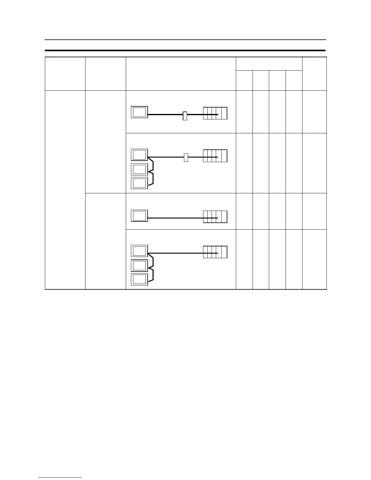
1:1 connection via a convertor unit
PT
Convertor unit
(NT-AL001)
Host
RS-485
(max. 500 m)
RS-232C
(max. 2 m)
f 99
RS-485
RS-232C
1:N connection via a convertor unit
PT
Host
Convertor unit
(NT-AL001)
RS-485
(total length 500 m)
RS232C
(max. 2 m)
f 104
RS-485
Direct 1:1 connection
PT
Host
RS-485 (max. 500 m)
f 138
RS-485
1:N connection
PT
Host
RS-485 (total length 500 m)
f 142
f: Connection possible : Connection not possible
- The RS-232C/RS-422A convertor unit (NT-AL001) requires +5 V, 150 mA at
pin 6 of the RS-232C connector. Check the signals of the RS-232C connector
at the host.
- +5 V is not output from serial port B of the NT31/NT31C. When connecting an
NT-AL001 at serial port B, a separate power supply is required for the NT-
AL001.
- The cable of an NT-AL001 cannot be connected or disconnected while the
power is ON. Always connect or disconnect the cable while the power supply
from the RS-232C cable is OFF (while the host power supply is OFF).
- NT link (1:N) connection is possible even when RS-232C is used at the
NT31/NT31C side for communication with the host, but in this case one NT-
AL001 unit is required for each NT31/NT31C. In this case, it is convenient to
use serial port A of the NT31/NT31C. +5 V is not output from serial port B.