74
Connecting to the RS-232C Port at the Host
Section 4-1
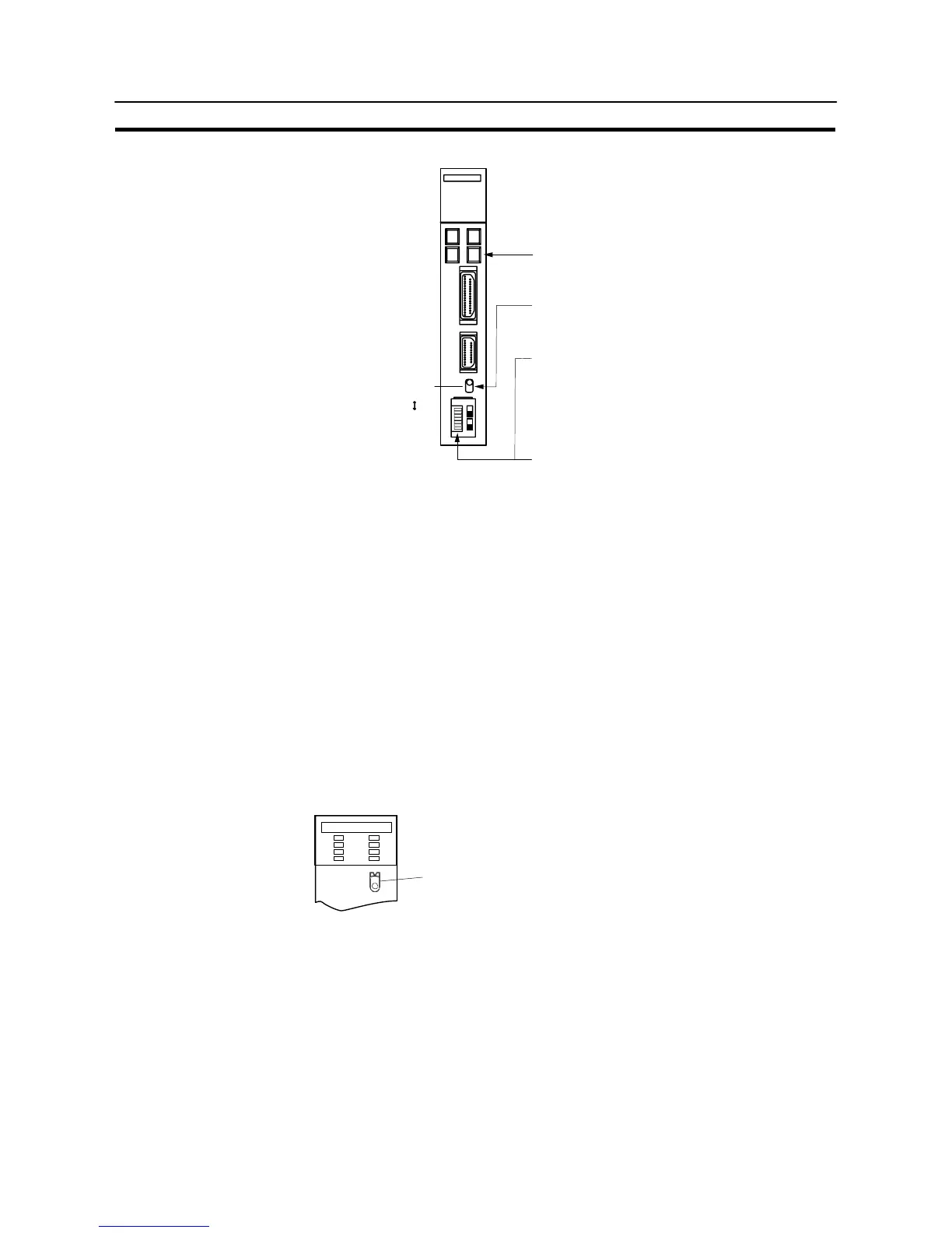
[Setting the front switches]
RS-232C
Communications port 1
(RS-232C)
Communications port 2
(RS-232C/RS-422A)
I/O port selector switch
RS-422A
@ Unit # (SW3, SW4)
When using communication port 2, set these
switches to “0”.
@ Communication condition setting (DIP SW1)
Set this switch to “OFF”.
Communication is executed in accordance with the
CPU bus unit system settings made at the PC. The
initial values for the system settings are as follows.
- Communications speed: 9600 bps
- Parity: Even
- Xon/Xoff control: Not executed
- Communication method: Full duplex
- Stop bits: 2 stop bits
- Data length: 7 bits
@ I/O port selection (selector switch)
Set this to “RS-232C”.
@ CTS selection (DIP SW2 and SW3)
Set SW2 or SW3 to “ON”. (Set this always to “0V”.)
To use communication port 1, set SW2. To use
communication port 2, set SW3.
S Connecting to a CS1 series serial communication unit
CS1 series backplate mounted type: CS1W–SCU21–E
[Setting the front switches]
Set the unit number of the serial communication unit by using the rotary switch lo-
cated on the front panel. Set each switch with a flat blade screwdriver so that the
values or symbols in the setting value window agree with the following.
Set the unit number to “0” through “F” so
that it will not overlap with the numbers
used in other units.
SCU21
RUN
ERC
SD1
RD1
RDY
ERH
SD2
RD2
UNIT
No.
F
E
D
C
B
A
9
8
7
6
5
4
3
2
1
0