4 Installation and Wiring
4 - 2
NX-series Digital I/O Unit User’s Manual (W521)
4-1 Installing NX Units
This section describes how to install NX Units.
Refer to the user's manual for the CPU Unit or Communications Coupler Unit to which NX Units are
connected for information on preparations of installation and installation in a control panel.
This section describes how to mount two NX Units to each other.
Always turn OFF the power supply before you mount NX Units.
Always mount NX Units one at a time. If you attempt to mount multiple NX Units that are already con-
nected together, the connections between the NX Units may separate from each other and fall.
• Do not apply labels or tape on the NX Units. When the Unit is installed or removed, adhesive
or scrap may adhere to the pins of the NX bus connector, which may cause malfunctions.
• Do not touch the pins in the NX bus connector on the Unit. Dirt may adhere to the pins in the
NX bus connector, which may result in malfunctions.
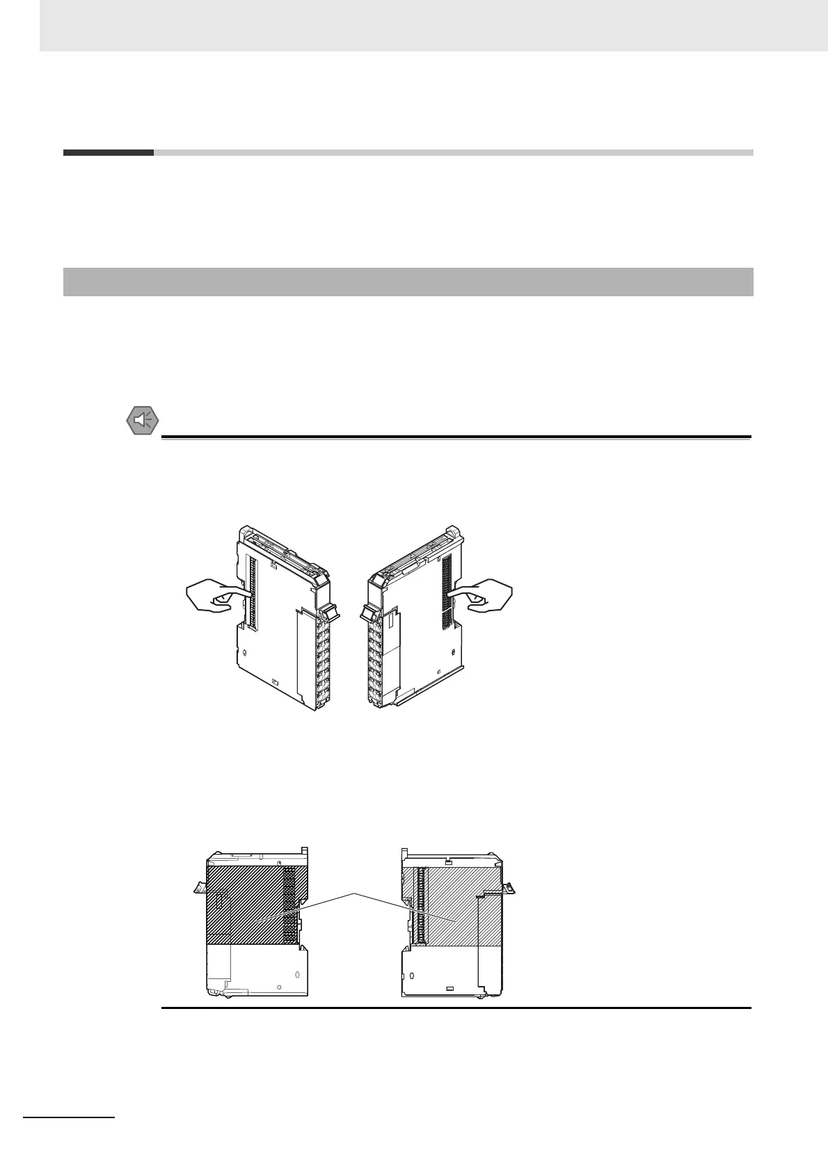
• Do not write on an NX Unit with ink within the restricted region that is shown in the following
figure. Also do not get this area dirty. When the Unit is installed or removed, ink or dirt may
adhere to the pins in the NX bus connector, which may result in malfunctions in the CPU
Rack or the Slave Terminal.
Refer to the user’s manual for the connected CPU Unit or Communications Coupler Unit for
the restricted region of CPU Unit and Communications Coupler Unit.
4-1-1 Installing NX Units
Example: NX Unit (12 mm width)
NG NG
Restricted
region (shaded
portion)