3 Configuration Units
3 - 28
NX-series NX1P2 CPU Unit Hardware User’s Manual (W578)
Analog Input Specifications
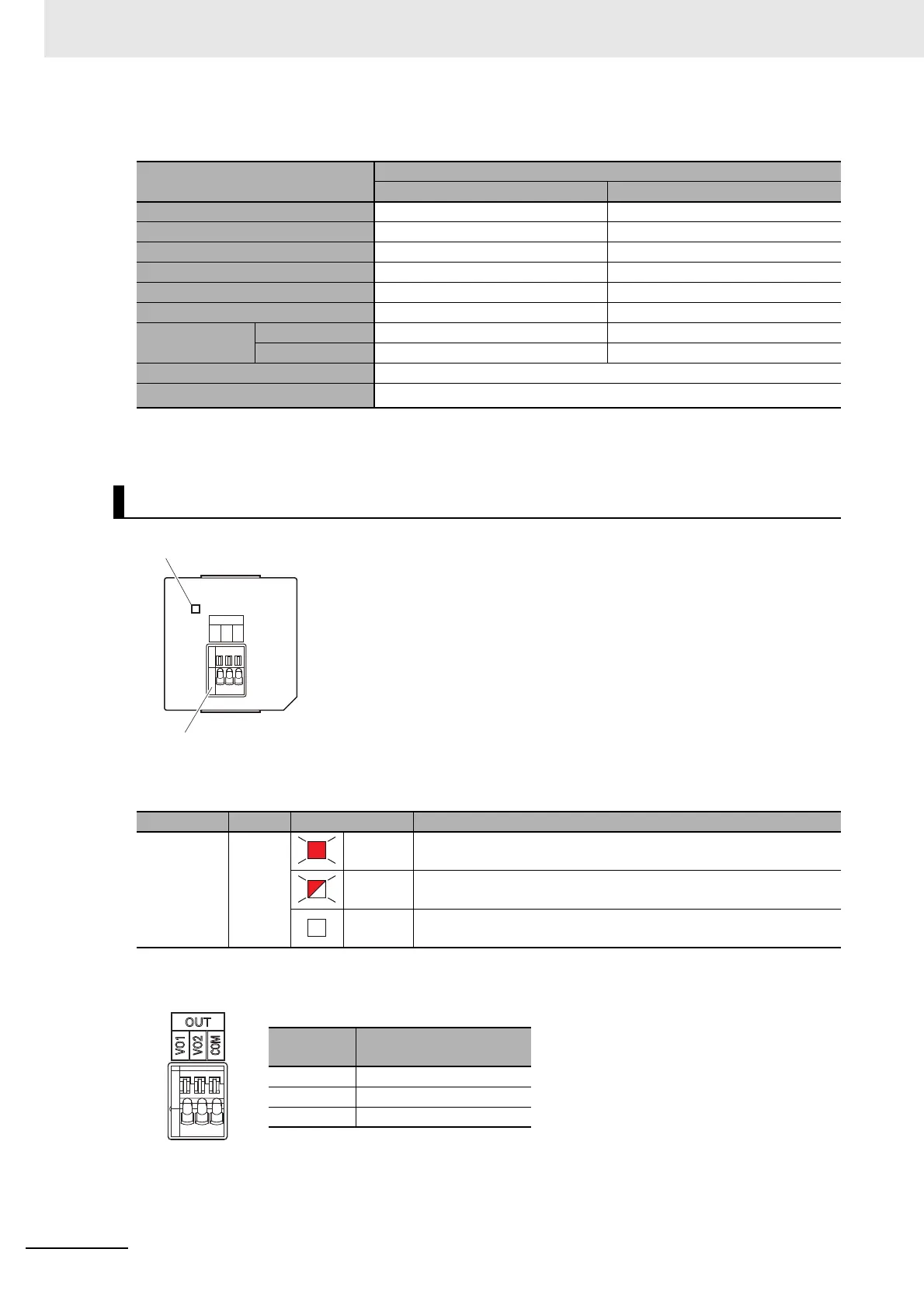
Status Indicator
Analog Output Terminal Array
Item
Specification
Voltage input Current input
Input method Single-ended input Single-ended input
Input range 0 to 10 V 0 to 20 mA
Input conversion range 0 to 10.24 V 0 to 30 mA
Absolute maximum rating -1 to 15 V -4 to 30 mA
Input impedance 200 k min. Approx. 250
Resolution 1/4,000 (full scale) 1/2,000 (full scale)
Overall accu-
racy
25°C ±0.5% (full scale) ±0.6% (full scale)
0 to 55°C ±1.0% (full scale) ±1.2% (full scale)
Averaging processing Not provided
Conversion time
Internal sampling time: 2 ms per point
*1
*1. Refer to the NX-series NX1P2 CPU Unit Built-in I/O and Option Board User’s Manual (Cat. No. W579) for in-
formation on refresh time.
Analog Output Option Board (NX1W-DAB21V)
Indicator Color Status Description
ERR Red Lit. An Option Board Error (WDT) was detected by the self-diagnostic
function.
Flashing. A Communications Error occurred between the Option Board and
the CPU Unit.
Not lit. Normal operation
Abbrevia-
tion
Signal name
VO1 Voltage output 1
VO2 Voltage output 1
COM Output common
ERR
OUT
VO1
VO2
COM
Analog output terminal block
Status indicator
 Loading...


