3 - 29
3 Configuration Units
NX-series NX1P2 CPU Unit Hardware User’s Manual (W578)
3-4 Analog I/O Option Board
3
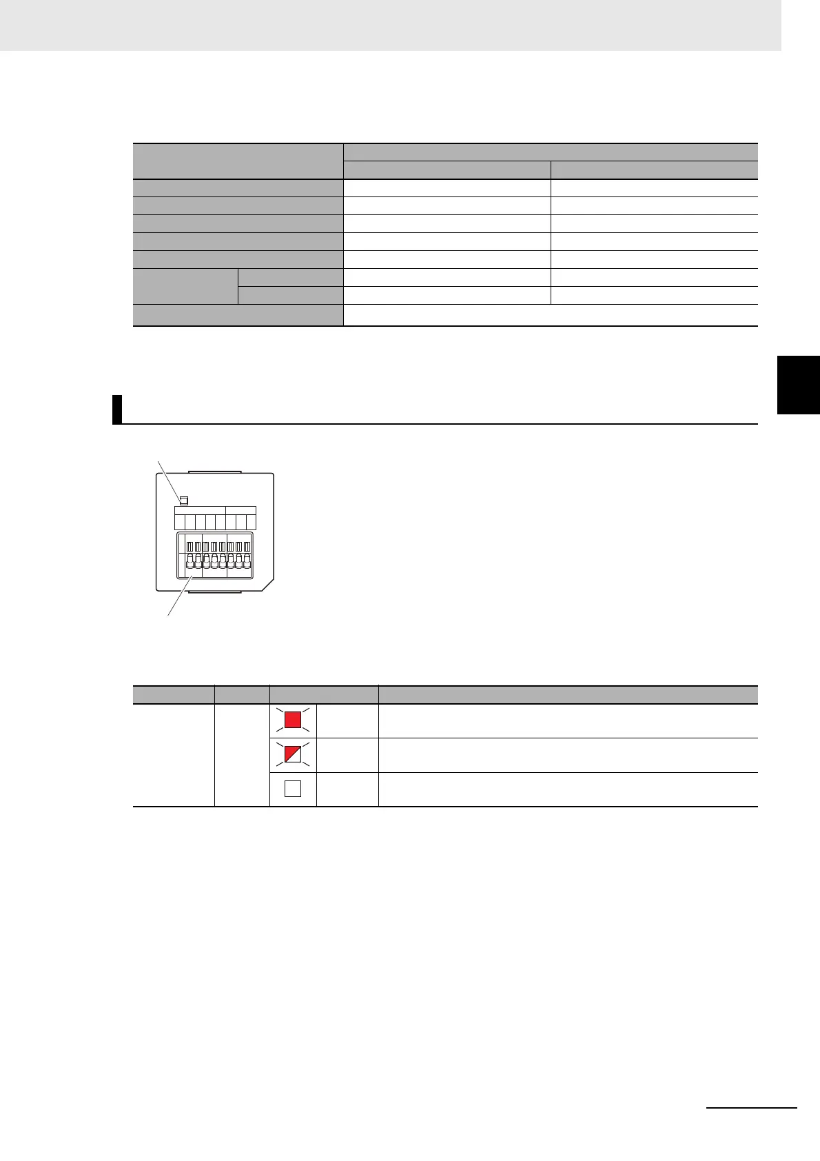
3-4-3 Part Names and Functions
Analog Output Specifications
Status Indicator
Item
Specification
Voltage output Current output
Output range 0 to 10 V ---
Output conversion range 0 to 10.24 V ---
Allowable load resistance 2 k min. ---
Output impedance 0.5 max. ---
Resolution 1/4,000 (full scale: 4,000) ---
Overall accu-
racy
25°C ±0.5% (full scale) ---
0 to 55°C ±1.0% (full scale) ---
Conversion time
Internal sampling time: 2 ms per point
*1
*1. Refer to the NX-series NX1P2 CPU Unit Built-in I/O and Option Board User’s Manual (Cat. No. W579) for in-
formation on refresh time.
Analog I/O Option Board (NX1W-MAB221)
Indicator Color Status Description
ERR Red Lit. An Option Board Error (WDT) was detected by the self-diagnostic
function.
Flashing. A Communications Error occurred between the Option Board and
the CPU Unit.
Not lit. Normal operation
ERR
OUT
VO1
VO2
COM
IN
VI1
I I1
VI2
I I2
COM
Analog output terminal block
Status indicator
 Loading...


