5 Installation and Wiring
5 - 60
NX-series NX1P2 CPU Unit Hardware User’s Manual (W578)
(d) Precautions on sensor inrush current
An incorrect input may occur due to sensor inrush current if a sensor is turned ON after the DC input
section has started up to the point where inputs are possible.
Determine the time required for sensor operation to stabilize after the sensor is turned ON and take
appropriate measures, such as inserting an ON delay into the user program after turning ON the
sensor.
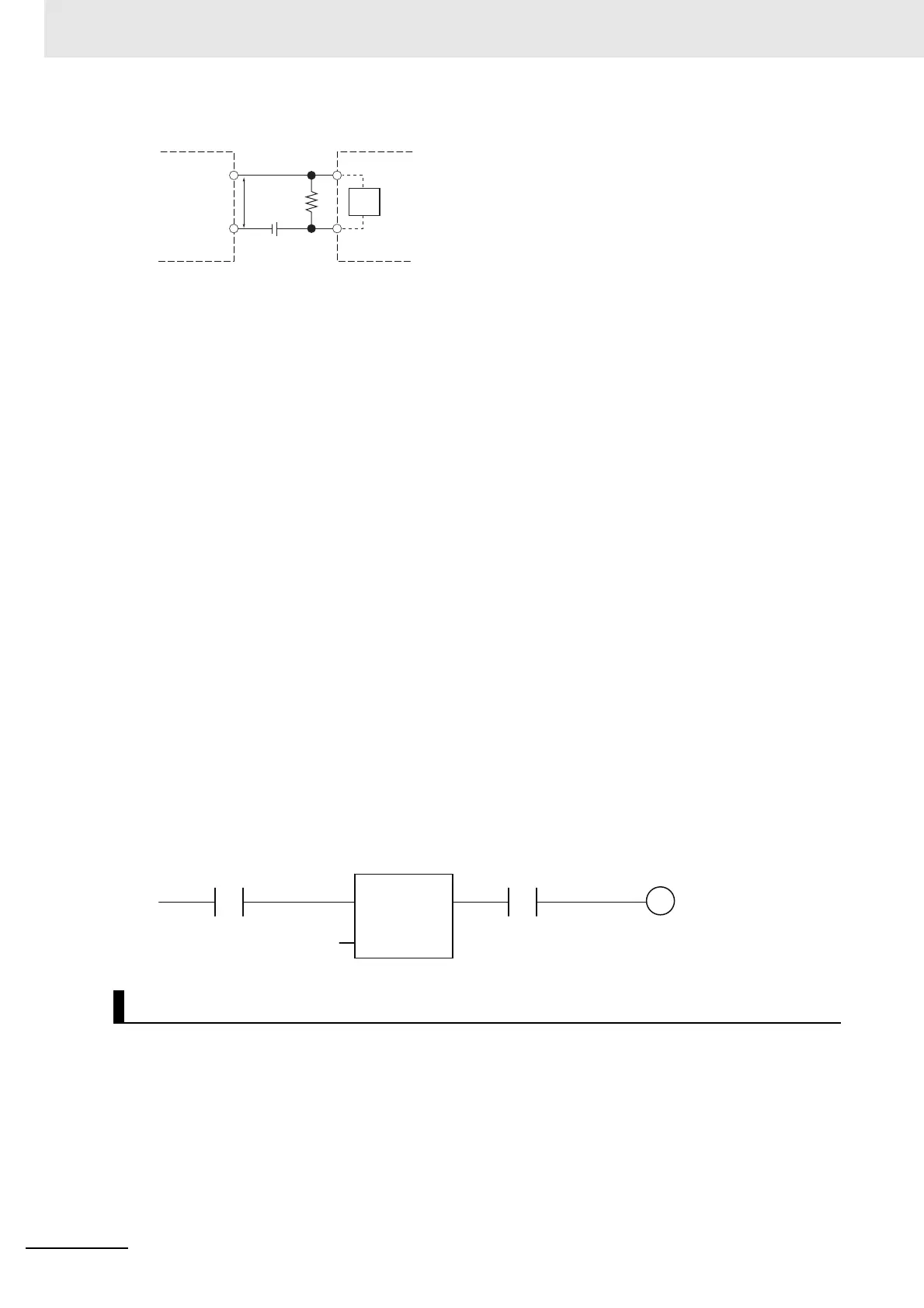
A programming example is shown below.
The sensor's power supply voltage is used as the input bit to Sensor_power.
A 100-ms timer delay (the time required for an OMRON Proximity Sensor to stabilize) is created in
the user program.
After the timer changes to TRUE, input bit X causes Output to change to TRUE after the input of the
sensor changes to TRUE.
If a load connected to the output terminals is short-circuited, output components and printed circuit
boards may be damaged. To guard against this, the PNP output type includes the short-circuit protec-
tion function.
When using the PNP output that does not include the short-circuit protection, incorporate a protective
fuse in the output circuit. Use a fuse with a capacity of around twice the rated output.
V
CC
: Power supply voltage V
R
: Sensor's output residual voltage
V
ON
: ON voltage of DC input I
OUT
: Sensor control output (load current)
V
OFF
: OFF voltage of DC input I
leak
: Sensor leakage current
I
ON
: ON current of DC input R: Bleeder resistor
I
OFF
: OFF current of DC input
R
IN
: Input resistor of DC input
Output Short-circuit Protection Function of the Built-in Output
DC input
RV
R
V
CC
Two-wire sensor
R
IN
TON
T#100ms
X Output
Sensor_power

 Loading...


