5 - 61
5 Installation and Wiring
NX-series NX1P2 CPU Unit Hardware User’s Manual (W578)
5-4 Wiring
5
5-4-9 Wiring the Built-in I/O
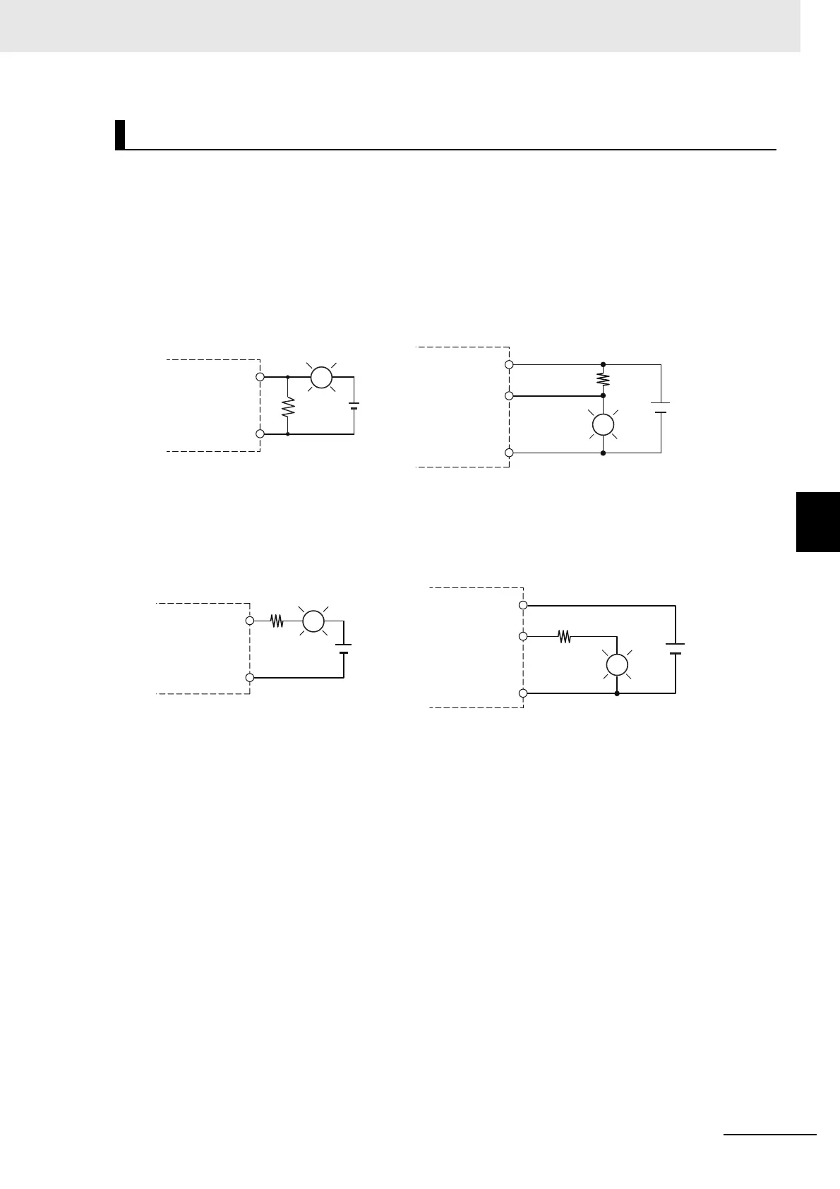
When connecting a transistor to an output device with a high inrush current (such as an incandescent
lamp), steps must be taken to avoid damage to the output transistor.
Use either of the following methods to reduce the inrush current.
Countermeasure 1
Draw about 1/3 of the current consumed by the load.
Countermeasure 2
Mount a limiting resistor.
In countermeasure 1, the current consumption from I/O power supply is increased although the voltage
supplied to the load L is not decreased.
In countermeasure 2, the voltage supplied to the load L is decreased although the current consumption
from I/O power supply is not increased.
Select the appropriate countermeasures according to the operating conditions.
Cn(0V) and Cn(+V) in the figure represent the common terminals, and 0Vn represents the terminal of
the power supply to drive the output circuit. Refer to Output Terminal Block on page 3-13 under 3-1-4
Terminal Blocks on page 3-10 for details.
Consideration for Inrush Current from Built-in Output
0Vn
Cn(+V)
OUT
L
OUT
Cn(0V)
R
L
+
NPN (sinking) type
Output
terminal block
Output
terminal block
PNP (sourcing) type
0Vn
Cn(+V)
OUT
L
R
OUT
Cn(0V)
+
L
NPN (sinking) type
Output
terminal block
Output
terminal block
PNP (sourcing) type

 Loading...


