9-17
9-3 Vibration Suppression Settings
OMNUC G5-series AC Servomotors and Servo Drives User’s Manual (with Built-in EtherCAT Communications)
9
Details on Servo Parameter Objects
Set the notch depth of resonance suppression notch filter 3.
Increasing the setting value shortens the notch depth and the phase lag.
While the adaptive filter is enabled, this object is set automatically.
Refer to 11-6 Adaptive Filter on page 11-18 and 11-7 Notch Filters on page 11-21.
Set the notch frequency of resonance suppression notch filter 4.
The notch filter function is disabled if this object is set to 5000.
While two adaptive filters are enabled, the resonance frequency 2 that is assumed by the adaptive
filter is automatically set. If no resonance point is found, the value 5000 is set.
Refer to 11-6 Adaptive Filter on page 11-18 and 11-7 Notch Filters on page 11-21.
Select the notch width of resonance suppression notch filter 4.
Increasing the setting value widens the notch width. Normally, use the default set value.
This object is automatically set when two adaptive filters are enabled.
Refer to 11-6 Adaptive Filter on page 11-18 and 11-7 Notch Filters on page 11-21.
Set the notch depth of resonance suppression notch filter 4.
Increasing the setting value shortens the notch depth and the phase lag.
While the adaptive filter is enabled, this object is set automatically.
Refer to 11-6 Adaptive Filter on page 11-18 and 11-7 Notch Filters on page 11-21.
Set the method to switch among four damping control filters.
Explanation of Set Values
*1 The set value 1 and 2 are for manufacturer's use only. Users are not allowed to set 1 and 2 for this
object.
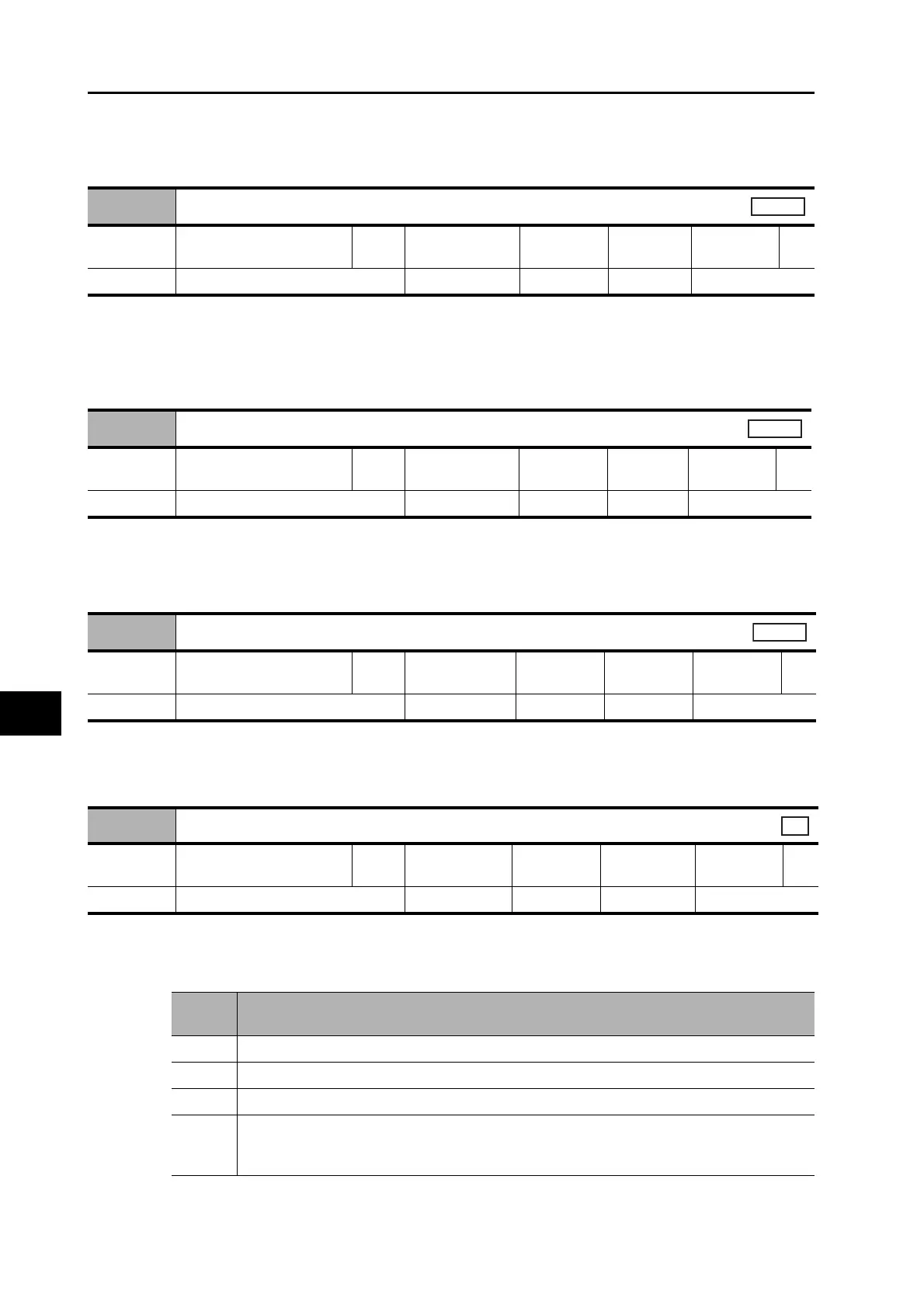
3210 hex
Notch 4 Frequency Setting
Setting
range
50 to 5000 Unit Hz
Default
setting
5000
Data
attribute
B
Size 2 bytes (INT16) Access RW PDO map Not possible.
All
3211 hex
Notch 4 Width Setting
Setting
range
0 to 20 Unit −
Default
setting
2
Data
attribute
B
Size 2 bytes (INT16) Access RW PDO map Not possible.
All
3212 hex
Notch 4 Depth Setting
Setting
range
0 to 99 Unit −
Default
setting
0
Data
attribute
B
Size 2 bytes (INT16) Access RW PDO map Not possible.
All
3213 hex
Damping Filter Selection
Setting
range
0 to 3 Unit −
Default
setting
0
Data
attribute
B
Size 2 bytes (INT16) Access RW PDO map Not possible.
csp
Set
value
Explanation
0 Up two damping filters, damping filters 1 and 2, can be used at the same time.
1 Reserved for manufacturer use
*1
2 Reserved for manufacturer use
*1
3
The damping filters are switched with position command direction.
• Forward direction: Damping filters 1 / 3 enabled
• Reverse direction: Damping filters 2 / 4 enabled

 Loading...


