9-45
9-7 Special Objects
OMNUC G5-series AC Servomotors and Servo Drives User’s Manual (with Built-in EtherCAT Communications)
9
Details on Servo Parameter Objects
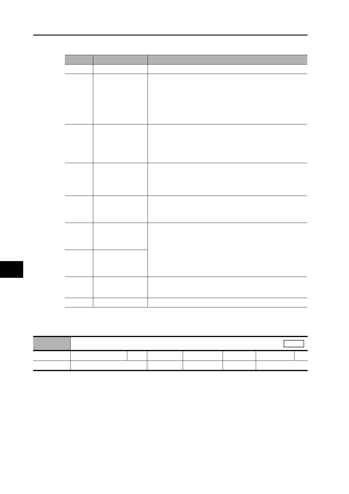
Explanation of Set Value
Set the time to indicate the node address when the control power is turned ON.
Set value Indicated item Description
0 Normal state Displays "−−" during Servo-OFF, and "00" during Servo ON.
1
Mechanical angle Displays a value between 0 and FF hex.
The value 0 indicates the zero position of the encoder.
The value increments when the motor rotates in the counterclockwise
(CCW) direction.
The value returns to 0 when it exceeds FF, but the count continues.
When an incremental encoder is used, it indicates "nF" (i.e., not fixed) is
displayed until the zero position of the encoder is detected after the control
power is turned ON.
2
Electric angle Displays a value between 0 and FF hex.
The value 0 indicates the position when the U-phase electro-motive force
shows the positive peak.
The value increments when the motor rotates in the counterclockwise
(CCW) direction.
The value returns to 0 when it exceeds FF, but the count continues.
3
Total number of
EtherCAT
communications
errors
*1
*1. The cumulative count of communication errors is cleared when the control power is cut OFF.
Displays a value between 0 and FF hex.
The cumulative count is saturated when it reaches the maximum value
(FFFF hex).
In this case, only the lowest order byte is shown.
The value returns to 00 when it exceeds FF, but the count continues.
4
Rotary switch setting
(node address)
Displays the rotary switch setting (i.e. node address) read at power-ON. The
displayed value is in decimal.
The value is not altered by any changes to the rotary switch setting after the
power-ON.
5
Total number of
encoder
communications
errors
*1
Displays a value between 0 and FF hex.
The cumulative count is saturated when it reaches the maximum value
(FFFF hex).
In this case, only the lowest order byte is shown.
The value returns to 00 when it exceeds FF, but the count continues.
6
Total number of external
encoder
communications
errors
*1
7
Z-phase counter
*2
*2. The value read from the encoder is indicated directly, regardless of the External Feedback Pulse Direction
Switching (3326 hex).
Displays the Z-phase count value read from the external encoder when an
incremental external encoder is used during fully-closed control. The value
between 0 an FF hex is displayed.
8 or over Unused Do not set anything.
3701 hex
Power ON Address Display Duration Setting
Setting range 0 to 1000 Unit 100 ms Default setting 0 Data Attribute R
Size 2 bytes (INT16) Access RW PDO map Not possible.
All

 Loading...


