A-99
Appendicies
G5 Series AC Servo Drives With Built-in EtherCAT Communications, Linear Motor Type
A-3 Sysmac Error Status Codes
App
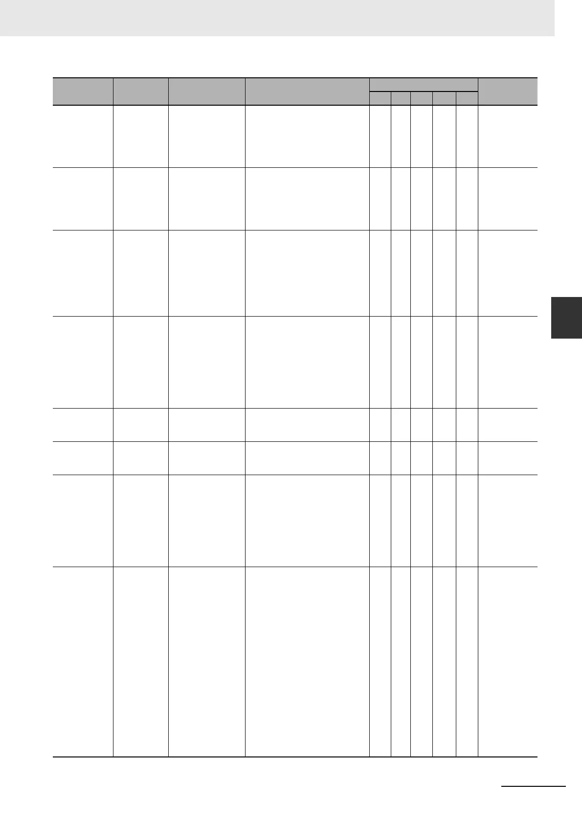
A-3-1 Error Table
38490000 hex Interface
Output
Function
Number Error
1
There is an
undefined number
specification in the
output signal
(OUTM1) function
allocation.
• There is an undefined number
specification in the output
signal (OUTM1) function
allocation.
page A-136
384A0000 hex Interface
Output
Function
Number Error
2
There is an
undefined number
specification in the
output signal
(OUTM2) function
allocation.
• There is an undefined number
specification in the output
signal (OUTM2) function
allocation.
page A-136
384B0000 hex External
Latch Input
Allocation
Error
There is an error in
the latch input
function allocation.
• The latch input was allocated to
an input signal other than IN5,
IN6, or IN7.
• A latch input is assigned to an
NC signal.
• The same latch input is not
assigned to the same pin in all
Control Modes.
page A-137
384C0000 hex Overrun Limit
Error
The motor
exceeded the
allowable operating
range set in the
Overrun Limit
Setting (3514 hex)
with respect to the
position command
input range.
• The gain or mass ratio is not
suitable.
• The set value of the Overrun
Limit Setting (3514 hex) is too
small.
page A-137
384F0000 hex Object
Setting Error
1
The electronic gear
ratio exceeded the
allowable range.
• The electronic gear ratio
exceeded the allowable range.
page A-138
38500000 hex Object
Setting Error
2
External encoder
ratio exceeded the
allowable range.
• External encoder ratio
exceeded the allowable range.
page A-138
38510000 hex External
Encoder
Connection
Error
The set value of the
External Feedback
Pulse Type
Selection (3323
hex) differs from the
external encoder
type that is
connected for serial
communications.
• The set value of the External
Feedback Pulse Type Selection
(3323 hex) differs from the
external encoder type that is
connected f
or serial
communications.
page A-139
38520000 hex Function
Setting Error
The function that
was set does not
support the
communications
period.
• The electronic gear object ratio
was not 1:1 when the
communications period was set
to 250 or 500 s.
• Modes of operation (6060 hex)
was set to pp or hm when the
communications period was set
to 250 or 500 s.
• More than 20 bytes were
mapped for RxPDO when the
communications period was set
to 250 s.
• No bytes (i.e., no objects) were
mapped for RxPDO.
• More than 10 objects were
mapped for RxPDO.
• More than 11 objects were
mapped for TxPDO.
page A-140
Event code Event name Meaning Assumed cause
Level
Reference
Maj Prt Min Obs Info

 Loading...

