,
Model
3G3SV
Inverter
capacity
Terminal symbol Terminal
screw
Wire size AWG Wire type
B2002 0.7 KVA L1 (R), L2 (S), L3 (T), B1 B2 T1 (U),
T2 (V), T3 (W)
M4 2-5.5 mm
2
14-10
Power
cable:
BB002 G(E)
600 V vinyl
B2004 1.3 KVA L1 (R), L2 (S), L3 (T), B1 B2 T1 (U),
T2 (V), T3 (W)
M4 2-5.5 mm
2
14-10
lead or
equivalent
BB004 G(E)
B2007 2.2 KVA L1 (R), L2 (S), L3 (T), B1 B2 T1 (U),
T2 (V), T3 (W)
M4 2-5.5 mm
2
14-10
BB007 G(E)
B2015 2.8 KVA L1 (R), L2 (S), L3 (T), B1 B2 T1 (U),
T2 (V), T3 (W)
M4 3.5-5.5 mm
2
12-10
BB015 G(E) 2-5.5 mm
2
14-10
B2022 4.7 KVA L1 (R), L2 (S), L3 (T), B1 B2 T1 (U),
T2 (V), T3 (W)
M5 3-5.8 mm
2
12-10
BB022 G(E) 2-8 mm
2
14-10
B2037 7.5 KVA L1 (R), L2 (S), L3 (T), B1 B2 T1 (U),
T2 (V), T3 (W)
M5 3-5.8 mm
2
12-10
BB037 G(E) 2-8 mm
2
14-10
Important
Lead size should be determinedconsidering voltage drop of leads.
Grounding Ground the casing of the 3G3SV using ground terminal G (E).
1, 2, 3...
1. Ground resistance should be 100
or less.
2. Never ground the 3G3SV in common with welding machines,
motors, and other large-current electrical equipment, or
ground pole. Run the ground lead in a separate conduit from
leads for large-current electrical equipment.
3. Use the ground leads which comply with AWG standards and
make the length as short as possible.
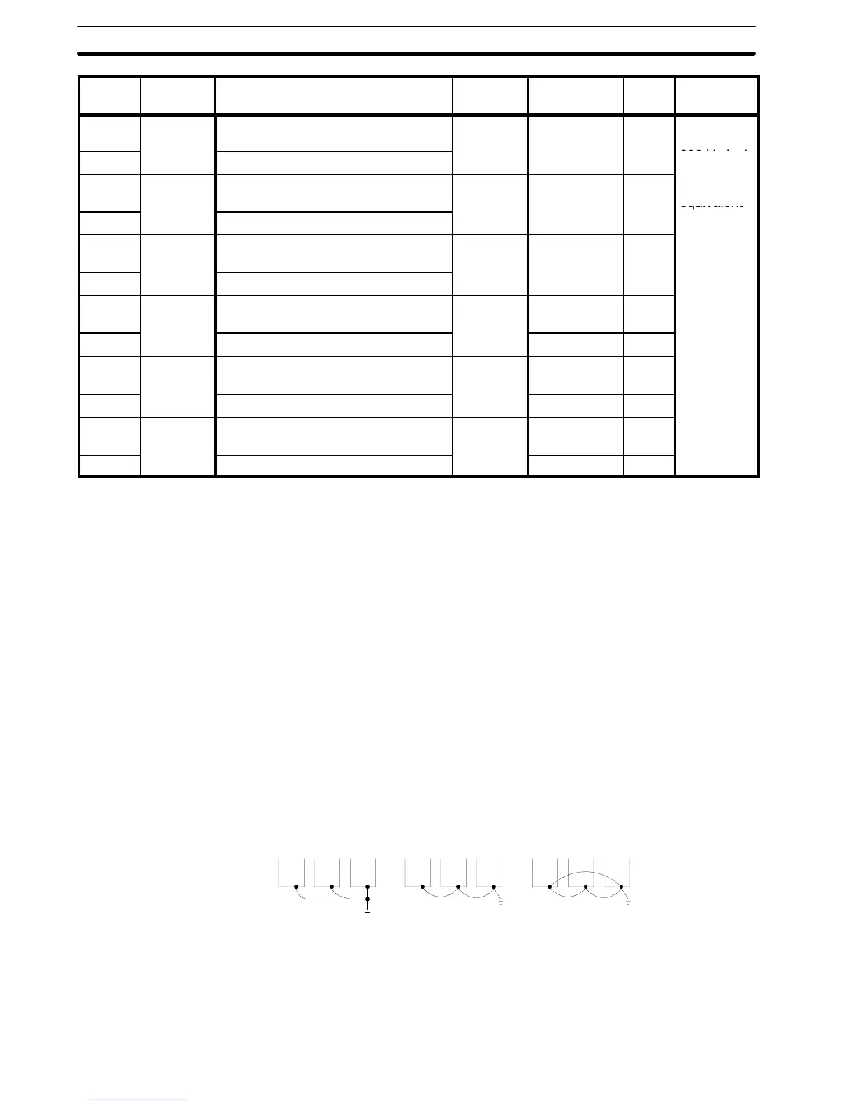
4. Where several 3G3SV units are used side by side, all the units
should preferably be grounded directly to the ground poles.
However, connecting all the ground terminals of 3G3SV in par-
allel, and grounding only one of 3G3SV to the ground pole is
also permissible (Fig. 4). However, do not form a loop with the
ground leads.
Good
(a)
Good
(b)
Poor
(c)
Fig. 3 Grounding of Three 3G3SV Units
1-4-2 Control Circuit Wiring
Control Signal Fig. 4 shows the relationship between I/O signals and screw termi-
nal numbers.
Section 1-4