(
When a ground faultinterrupteris used select the one with no influ-
ence for high frequency, and setting current should be 200 mA or
over and operating time, 0.1 sec or over to prevent malfunction.
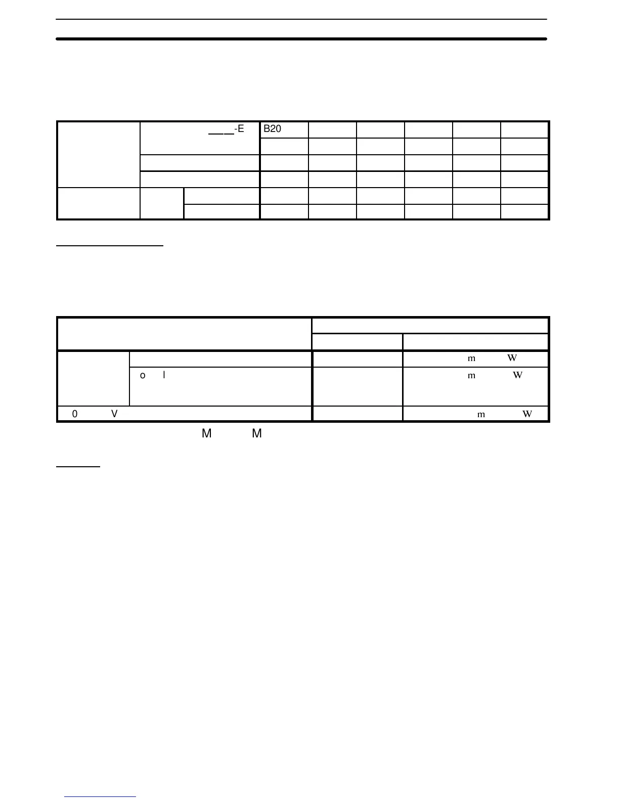
Table 1 Molded-case Circuit Breakers and Magnetic Contactors
Model 3G3SV-
-E B2002 B2004 B2007 B2015 B2022 B2037
BB002 BB004 BB007 BB015 BB022 BB037
3
3
Capacity 0.7 kVA 1.3 kVA 2.2 kVA 2.8 kVA 4.7 kVA 7.5 kVA
Rated output current 1.5 A 3A 5A 6.5 A 11 A 17.5 A
Molded-case
Rated
3-phase 5A 5A 10A 20A 20A 30A
Circuit Breaker current
Single-phase 5A 10A 20A 20A 40A 50A
Surge Absorber
The surge absorbers should be connected to the coils of relays,
magnetic contactors, magnetic valves, or magnetic relays. Select
thetypefromTable2.
Table 2 Surge Absorbers
Coils of magnetic contactor and control relay Surge absorber (see note)
Model Specifications
200 to 230 V Large-size magnetic contactors DCR2-50A22E 250 VAC, 0.5
F+20
Control relay
LY-2, -3 (OMRON)
MM-2, -4 (OMRON)
DCR2-10A25C 250 VAC, 0.1
F + 100
400 to 460 V units DCR2-50D100B 1,000 VDC, 0.5
F + 220
Note Made by MARCON Electronics. Marketed in Japan.
Wiring
Main Circuit Input/Output
1, 2, 3...
1. Phase rotation of input terminals L1 (R), L2 (S), L3 (T) is avail-
able in either direction, clockwise and counterclockwise.
2. When inverter output terminals T1 (U), T2 (V), and T3 (W) are
connected to motor terminals T1 (U), T2 (V), and T3 (W), re-
spectively, motor rotates counterclockwise, viewed from oppo-
site drive end, upon forward operation command. To reverse
the rotation interchange any two of motor leads.
3. Never connect AC main circuit power supply to output termi-
nals T1 (U), T2 (V), and T3 (W).
4. Care should be taken toprevent contact of wiringleads withthe
3G3SV cabinet, or a short-circuit may result.
5. Never connect power factor correction capacitor or noise filter
to 3G3SV output.
6. Never open or close contactors in the output circuit unless in-
verter is properly sized.
Wire Size Table 3 shows wire sizes and types.
Section 1-4