-
1-7-3 Inverter Monitor Display
The inverter display unit (3-digit LED) provided for the standard
models has the following display, disregarding the modes (drive
mode, program mode).
Display contents can be selected by the 1st digit of constant 21
monitor selection.
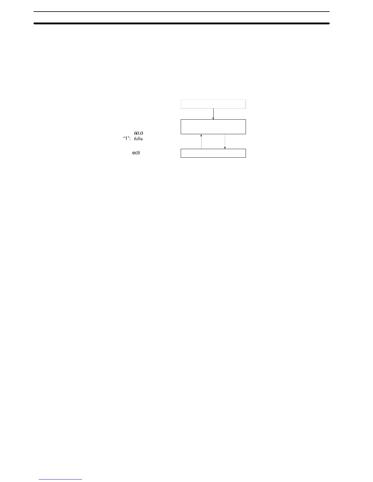
Output frequency display
or output current display
Protection/alarm display
Power on
“0”: Output frequency
“1”: Output current
“0”:
“1”:
Protection/alarm display
No minus display even in re-
verse run.
Less than 100 Hz:
1 digit below decimal point
100 Hz or more:
No digit below decimal point
Less than 10 A:
1 digit below decimal point
10 A or more:
No digit below decimal point
Fault reset Fault
occurrence
1-7-4 Corrective Action for Motor Faults
Table 6 shows the check points and corrective actions of motor
faults.
Section 1-7