-
Caution To house multiple SYSDRIVE 3G3SVs in a switchgear, install a
cooling fan or some other means to cool the airentering the invert-
er below 1139F(459C).
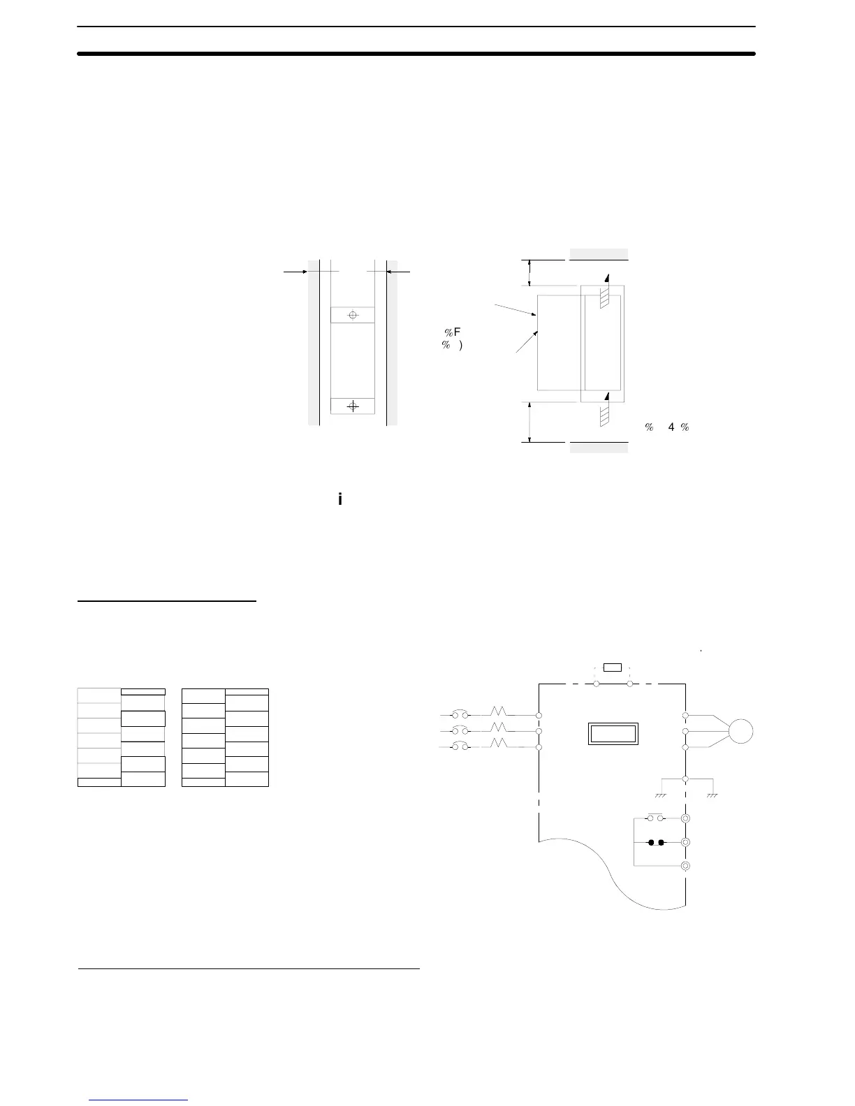
1-3-2 Mounting Space
Install the 3G3SV vertically and allow sufficient space for effective
cooling as shown in Fig. 1.
0.39 in (10 mm)
or more
0.39 in (10 mm)
or more
(a) Front View. (b) Side View
AIR
AIR
4.7 in (120 mm)
or more
Allowable tem-
perature of
control part:
131
F
(55
C)
Front cover
4.7 in (120 mm)
or more
Open chassis type:
113
F(45
C)
Fig. 1 Mounting Space
1-4 Wiring
1-4-1 Main Circuit
Main Circuit W
iring
Connect wiring as shown in Fig. 2.
IM
L1 (R)
L2 (S)
L3 (T)
L1 (R)
L2 (S)
L3 (T)
T1 (U)
T2 (V)
T3 (W)
G(E)
FLT-A
FLT-B
FLT-C
B1 B2
Motor
MCCB
3-phase power supply
200/208/220 V, 50 Hz
200/208/220/230 V,
60 Hz
Fault
contact
output
L
1
(R)
L
2
(S)
L
3
(T)
T
1
(U)
T
2
(V)
T
3
(W)
L
1
(R)
L
2
(S)
T
1
(U)
T
2
(V)
T
3
(W)
Braking resistor or
braking resistor unit (optional)
Only terminal L1 (R),L2 (S)
for single-phase power supply
Main Circuit Terminal Arrangement
Note: Circuit terminal block screw size is M4
3G3SV
FLT-A
FLT-B
FLT-C
B1
B2
E
FLT-A
FLT-B
FLT-C
B1
B2
E
3-phase input Single-phase input
Fig. 2 Main Circuit Wiring
Molded-case Circuit Breaker (MCCB)
Be sure to connect MCCBsbetween the power supply and 3G3SV
input terminals L1 (R), L2 (S), L3 (T). Recommended MCCBs are
listedinTable1.
Section 1-4