4-107
4-2 Function Mode
4
Functions
MP Adjustment
•Adjust the Inverter output gain according to the meter connected to the MP terminal.
Analog Output AM/AMI Terminals
You can monitor the output frequency and current using the AM and AMI terminals on the control
circuit terminal block.
The AM terminal provides 0- to 10-V analog output.
The AMI terminal provides 4- to 20-mA analog output.
AM/AMI Selection
•Select a signal to output from the following table.
*1. This output is enabled only when "SLV", "0-Hz SLV", or "V2" is selected. (Refer to "Control Method (V/f
Characteristics)" (page 4-21).)
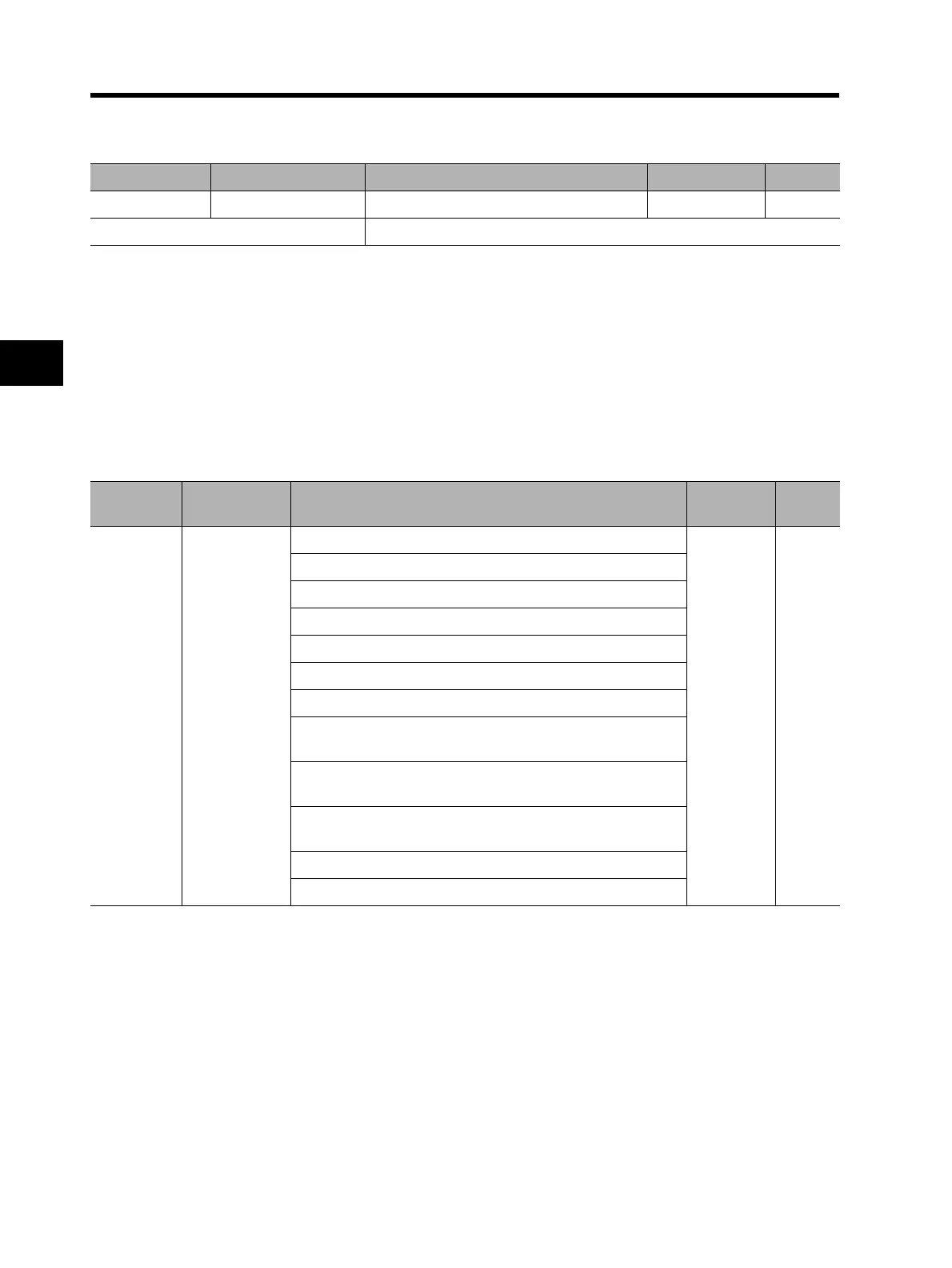
Parameter No. Function name Data Default setting Unit
C105 MP gain setting 50. to 200.: Set a gain for the MP monitor. 100. %
Related functions C027, b081
Parameter
No.
Function name Data
Default
setting
Unit
C028/C029
AM selection
/
AMI selection
00: Output frequency (0 to Max. frequency (Hz)
*3
)
00
01: Output current (0% to 200%)
02: Output torque
*1
(0% to 200%)
04: Output voltage (0% to 100%)
05: Input voltage (0% to 200%)
06: Thermal load rate (0% to 100%)
07: LAD frequency (0 to Max. frequency [Hz])
09: Motor temperature (0°C to 200°C) (0°C output at 0°C or
lower)
10: Fin temperature
(0°C to 200°C) (0°C output at 0°C or lower)
11: Output torque (signed)
(AM output only. 0% to 200%
*1 *2
)
13: Not used
14: Not used
 Loading...


