4-123
4-3 Functions When Option PG Board (3G3AX-PG01) Is Used
4
Functions
Frequency reference for the pulse train position control mode is calculated with the following formu-
la:
In the position control mode, the acceleration/deceleration time settings are disabled. (The Inverter
is automatically brought into LAD cancel status.)
The higher the position loop-back gain, the shorter the acceleration/deceleration time.
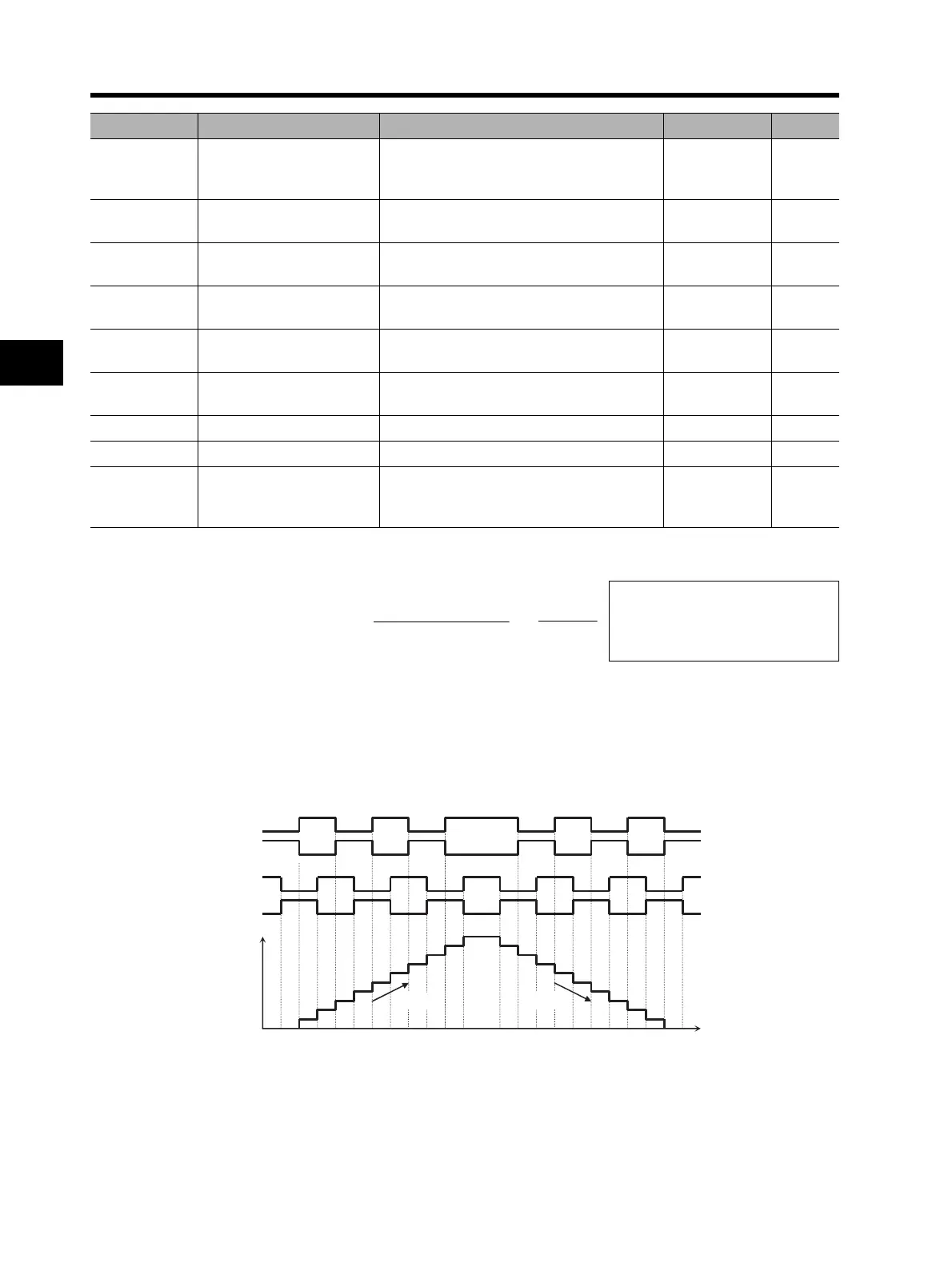
For details on the pulse train input mode, refer to the following.
•Mode 0: Pulse train with 90° phase difference
P017
Position ready
range setting
0. to 9999./1000 (10000):
Set a value equivalent to encoder ×4
multiplication.
5.
P018
Position ready
delay time setting
0.00 to 9.99 0.00 s
P019
Electronic gear setting
position selection
00: FB (feedback side)
01: REF (command side)
00
P020
Electronic gear ratio
numerator
1. to 9999. 1.
P021
Electronic gear ratio
denominator
1. to 9999. 1.
P022
Position control
feedforward gain
0.00 to 99.99/100.0 to 655.3 0.00
P023 Position loop gain 0.00 to 99.99/100.0 0.50 rad/s
P024 Position bias amount -204 (-2048)/-999. to 2048. 0.
C001 to C008
Multi-function inputs
1 to 8 selection
47: PCLR (position deviation clear)
48: STAT (pulse train position command
input permission)
Parameter No. Function name Data Default setting Unit
P : Number of motor poles
Kv : Position loop gain
ENC : Number of encoder pulses
∆P : Position deviation
Frequency reference (Hz) =
6.4 × P × Kv
ENC
×
∆P
255
SAP
SAN
SBP
SBN
(Pulse train input)
(Pulse train input)
Detected
pulses
Time
Forward Reverse