4-140
4-4 Communication Function
4
Functions
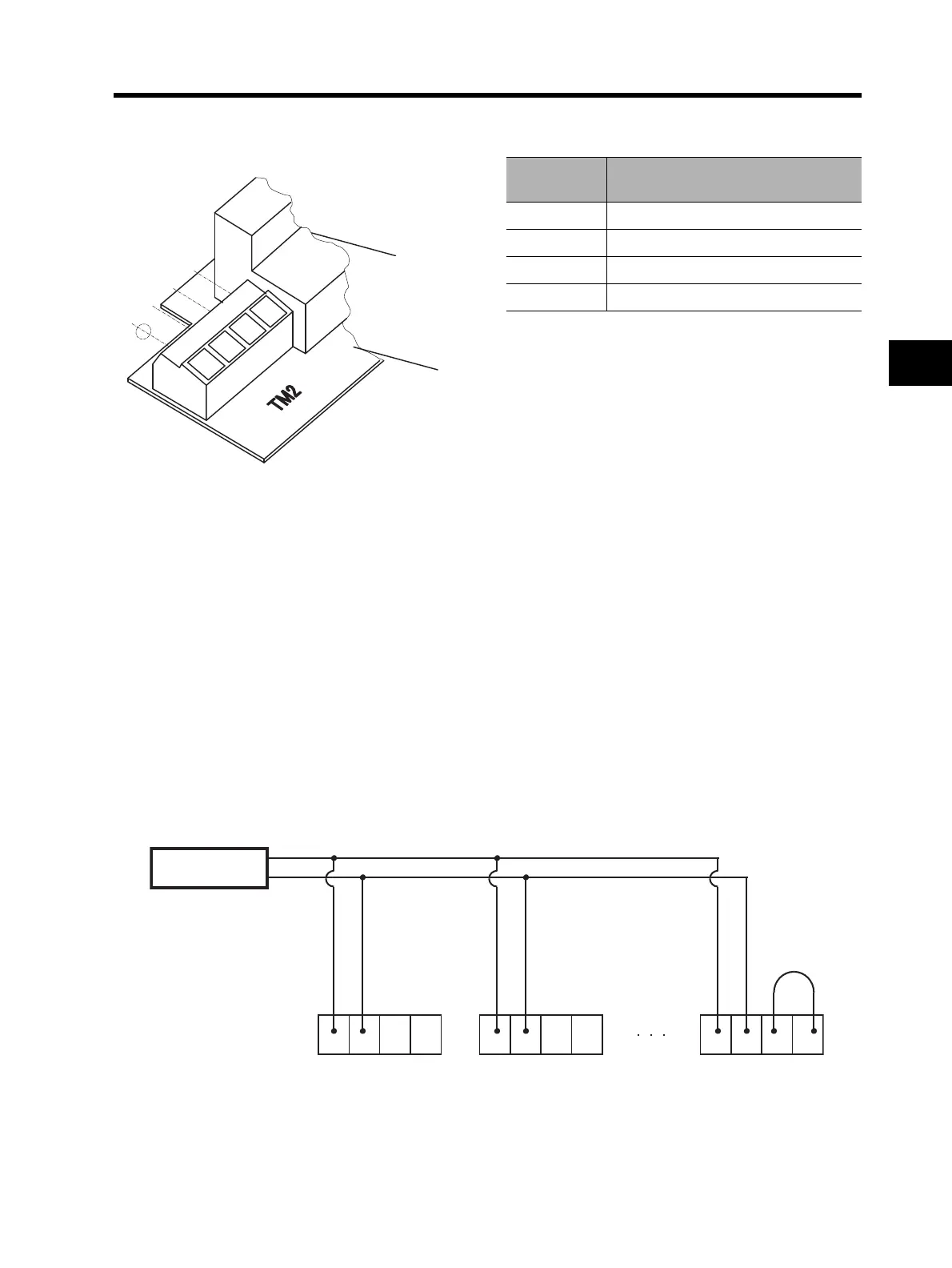
<RS485 Port Specifications and Connections>
For the RS485 communication function, use the TM2 terminal on the control terminal block board.
The following wires are recommended for TM2:
Single wire 0.14 to 1.5 mm
2
(If two equal-sized wires are connected to one pole:
0.14 to 0.5 mm
2
)
Stranded wire 0.14 to 1.0 mm
2
(If two equal-sized wires are connected to one pole:
0.14 to 0.2 mm
2
)
Stranded wire with solderless terminal 0.25 to 0.5 mm
2
(Example: PC-1.25 F-7 from J.S.T. MFG. Co., Ltd.)
Wire strip length 5 mm
Tightening torque 0.22 to 0.25 N•m (screw size: M2)
•Connection
Connect the Inverters parallel to each other, as shown below. For the termination Inverter, short-
circuit the RP and RS- terminals. (Also, if the RS485 communication function is used with a single
Inverter, the RP and RS- terminals must be short-circuited.)
Short-circuiting the RP and RS- terminals activates the termination resistor inside the control
terminal block board, suppressing signal reflection.
Terminal
abbreviations
Description
RS+ Transmission/Reception (+)
RS- Transmission/Reception (-)
RP Termination resistor enabling terminal
RS- Termination resistor enabling terminal
Control terminal
block
Control terminal
block board
RS+RS+
RS-RS-
RPRP
RS-RS-
External controller
RS+ RS- RP RS- RS+ RS-
RP
RS- RS+ RS- RP RS-