2-16
2-2 Wiring
2
Design
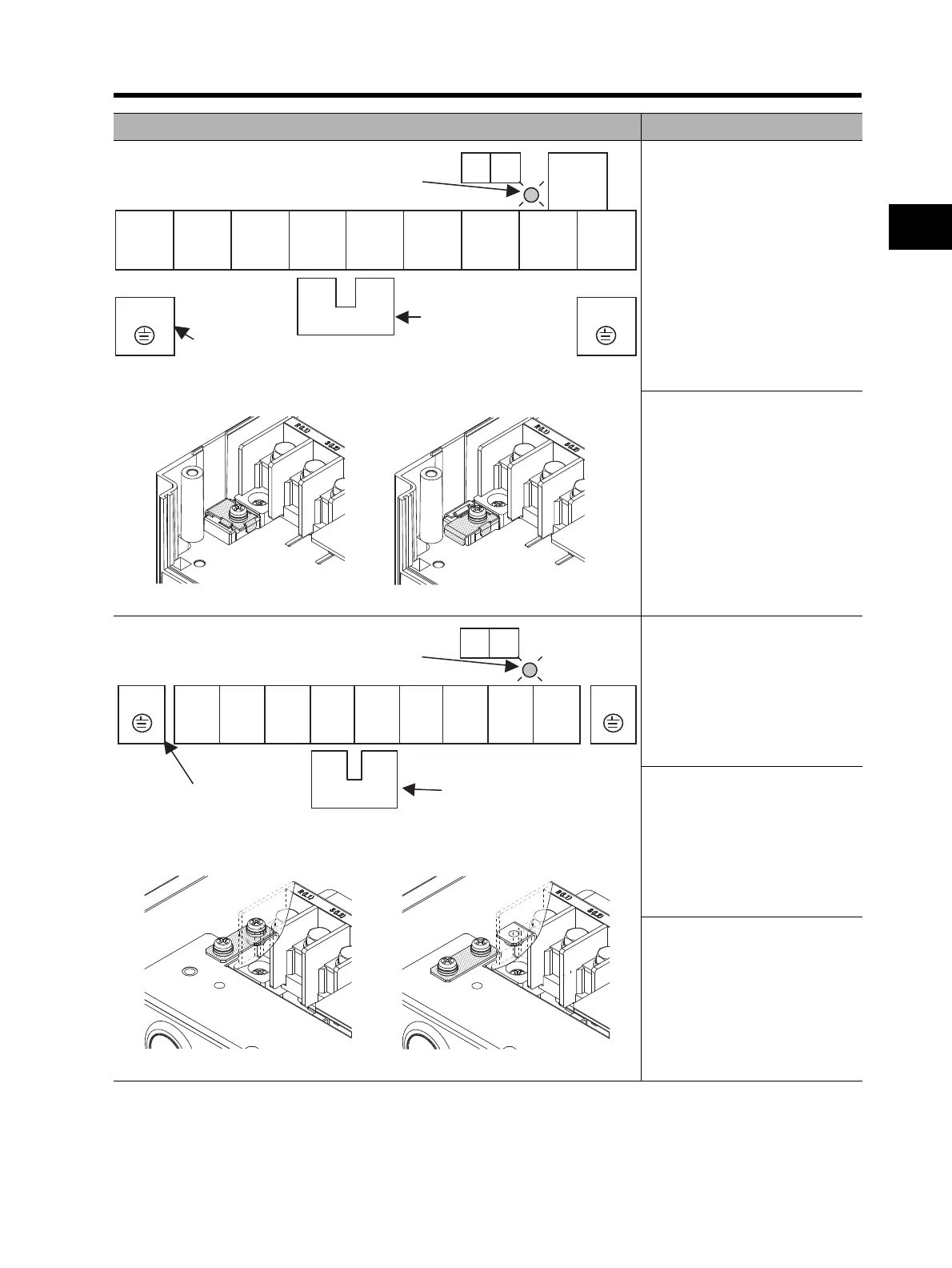
3G3RX-A2150 to A2185
3G3RX-A4150 to A4220
Ro,To: M4
Ground terminal: M6
Others: M6
[EMC filter function switching method]
3G3RX-A2220
Ro,To: M4
Ground terminal: M6
Others: M8
[EMC filter function switching method]
3G3RX-A2300
Ro, To: M4
Ground terminal: M6
Others: M8
3G3RX-A4300
Ro,To: M4
Ground terminal: M6
Others: M6
3G3RX-A2370
3G3RX-A4370
Ro,To: M4
Ground terminal: M8
Others: M8
Terminal arrangement Applicable model
Ro To
RB
R/L1 S/L2 T/L3 +1
P/+2 N/- U/T1 V/T2 W/T3
G
G
Ground terminal with short-circuit
bar (shaded area) for EMC filter
function switching
+1-P/+2 short-circuit bar
When not using the DC
reactor, keep the +1-P/+2
short-circuit bar attached.
CHARGE LED indicator
EMC filter enabled EMC filter disabled (factory default)
Ro To
R/L1 S/L2 T/L3 +1
P/+2 N/- U/T1 V/T2 W/T3
GG
Ground terminal with short-circuit
bar (shaded area) for EMC filter
function switching
When not using the DC reactor,
keep the +1-P/+2
short-circuit bar attached.
CHARGE LED indicator
+1-P/+2 short-circuit bar
EMC filter enabled EMC filter disabled (factory default)