Connecting destination of
Additional I/O Power Sup-
ply Unit
Model of Additional I/O Power
Supply Unit
Peak value Pulse width
NX1P2 CPU Unit NX-PF0730
20 A
*1
1 s
*1
NX-PF0630
• NX502 CPU Unit
• NX102 CPU Unit
• Communications Coupler
Unit
• Communication Control
Unit
NX-PF0730 50 A 1 s
NX-PF0630 20 A 1 s
*1. When the Additional I/O Power Supply Unit is connected to the NX1P2 CPU Unit, the value will be as
described on this table, regardless of the specification of the Additional I/O Power Supply Unit.
For the ratings of the Communications Coupler Unit or Communication Control Unit that can supply
I/O power, refer to a description of inrush current restrictions in the user’
s manual for the Communi-
cations Coupler Unit or Communication Control Unit.
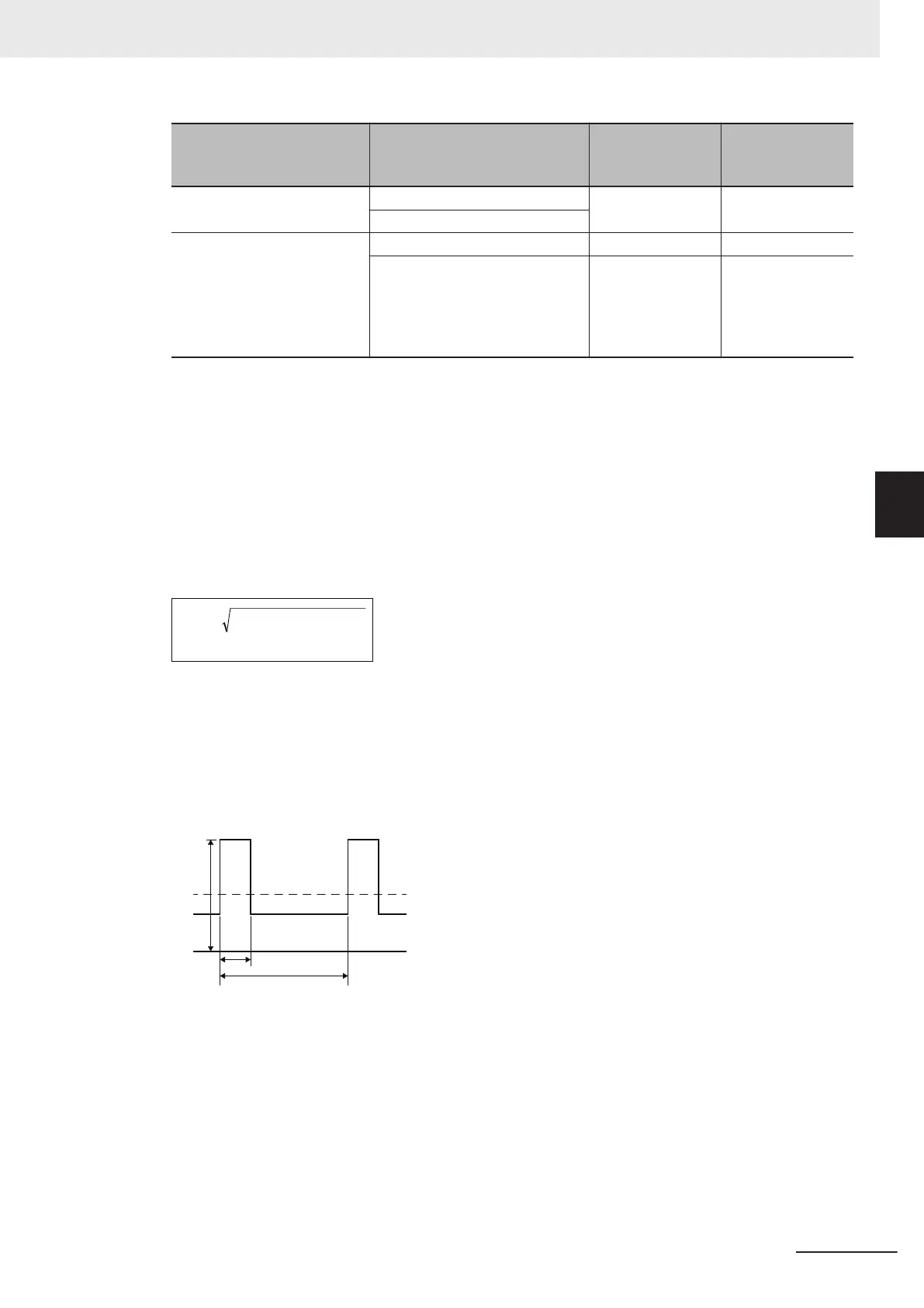
Calculating the effective value of the I/O power supply current
The following gives the equation to calculate the effective value of the I/O power supply current,
Irms.
Irms
= Ip
×
D
+
Ia
×
(1-
D
)
2 2
(D =
τ
/
T
)
Ip: Peak inrush current (A)
Irms: Effective value of the I/O power supply current (A)
Ia: T
otal current consumption from I/O power supply (A)
D: Inrush current duty
t: Inrush current pulse width (s)
T: Inrush current period (s)
For details on the current consumption from I/O power supply of the NX Units to be used, refer to
the user's manual for individual NX Units.
For details on calculating current consumption from I/O power supply, refer to the design of the I/O
power supply from the NX bus described in the user
’s manual for the connected CPU Unit, Com-
munications Coupler Unit, or Communication Control Unit.
4 Installation and Wiring
4-35
NX-series System Units User's Manual (W523)
4-6 Wiring the Additional Power Supply Units
4
4-6-2 Wiring the Additional I/O Power Supply Unit