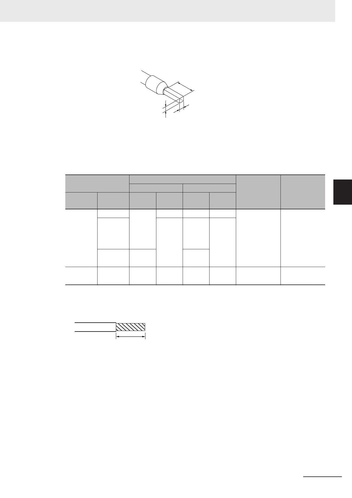
When you use any ferrules other than those in the above table, crimp them to the twisted wires so
that the following processed dimensions are achieved.
8 to 10 mm
2.
4 mm max. (except ground terminals)
2.7 mm max. (ground terminals)
1.6 mm max. (except ground terminals)
2.0 mm max. (ground terminals)
Using Twisted Wires/Solid Wires
If you use twisted wires or solid wires, use the following table to determine the correct wire specifi-
cations.
Terminals
Wire type
Wire size
Conductor
length (strip-
ping length)
Twisted wires Solid wires
Classifica-
tion
Current
capacity
Plated
Unplat-
ed
Plated
Unplat-
ed
All termi-
nals except
ground ter-
minals
2 A max. Possible Possible Possible Possible
0.08 to 1.5 mm
2
(AWG28 to 16)
8 to 10 mm
Greater
than 2 A
and 4 A or
less
Not pos-
sible
Possi-
ble
*1
Not pos-
sible
Greater
than 4 A
Possi-
ble
*1
Not pos-
sible
Ground
terminals
--- Possible
Possible Possi-
ble
*2
Possi-
ble
*2
2.0 mm
2
9 to 10 mm
*1. Secure wires to the screwless clamping terminal block. Refer to Securing Wires on page 4-51 for how to
secure wires.
*2.
With the NX-TB£££1 Terminal Block, use twisted wires to connect the ground terminal. Do not use a
solid wire.
Conductor length (stripping length)
4 Installation and Wiring
4-47
NX-series System Units User's Manual (W523)
4-9 Wiring the Terminals
4
4-9-1 Wiring to the Screwless Clamping Terminal Blocks