13
RFID System
Operation Manual
Section 1 Names and Functions of Components
Section 1
Product Overview
Names and Functions of Components
■ Power Supply and Ground Terminals
■ External I/O Port
Connect the external I/O port to the external I/O signals.
Name Description
Power supply terminals Supply 24 VDC.
Recommended power supply: S8VS-03024 (manufactured by OMRON)
Ground terminal This is the ground terminal. Connected a dedicated ground line grounded to 100 W or less.
Name Description
RUN Turns ON when the ID Controller is operating normally and communications are possible with the
host device.
BUSY Output from when a command is received from the host device until communications have been
completed.
ERROR Output for 500 ms when there is an error in Data Carrier communications, host device communica-
tions, or hardware. The output time can be changed with the SET PARAMETER (SP) command.
OUT1 User output 1, which can be manipulated using the CONTROL CONTROLLER (CC) command.
OUT2 User output 2, which can be manipulated using the CONTROL CONTROLLER (CC) command.
COM_O The output common terminal.
RST An external reset input for emergency stopping. The ID Controller will be reset when RST is input.
TRG/IN1 If pin 4 of SW4 (lower trigger setting) is ON, a RECEPTION COMPLETED command is executed
for Read/Write Head 1 on the rising edge of this input. If pin 4 of SW4 is OFF, this input is used as
user input 1, which can be read with the CONTROL CONTROLLER (CC) command.
TRG/IN2 If pin 4 of SW4 (lower trigger setting) is ON, a RECEPTION COMPLETED command is executed
for Read/Write Head 2 on the rising edge of this input. If pin 4 of SW4 is OFF, this input is used as
user input 2, which can be read with the CONTROL CONTROLLER (CC) command.
COM_I The input common terminal.
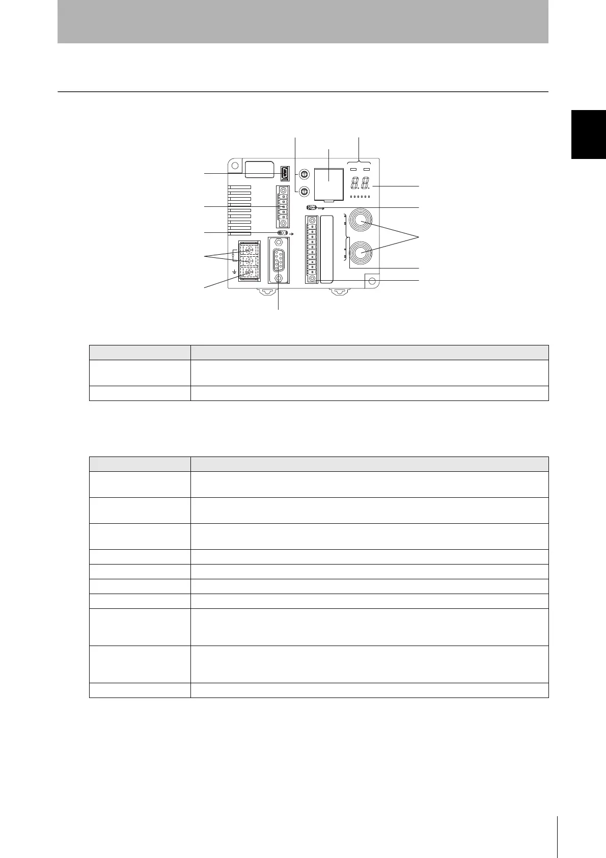
USB port
RS-422/RS-485 port
Power supply terminals
Ground terminal
RS-232C port
Switch cover
Main display indicators
Monitor display
Read/Write Head
connection port
External I/O port
Head operation indicators
Controller
number switches
Mode switch
Terminating resistance switch

 Loading...


