RFID System
Operation Manual
Section 7 Specifications and Dimensions
Section 7
Appendix
151
I/O Specifications
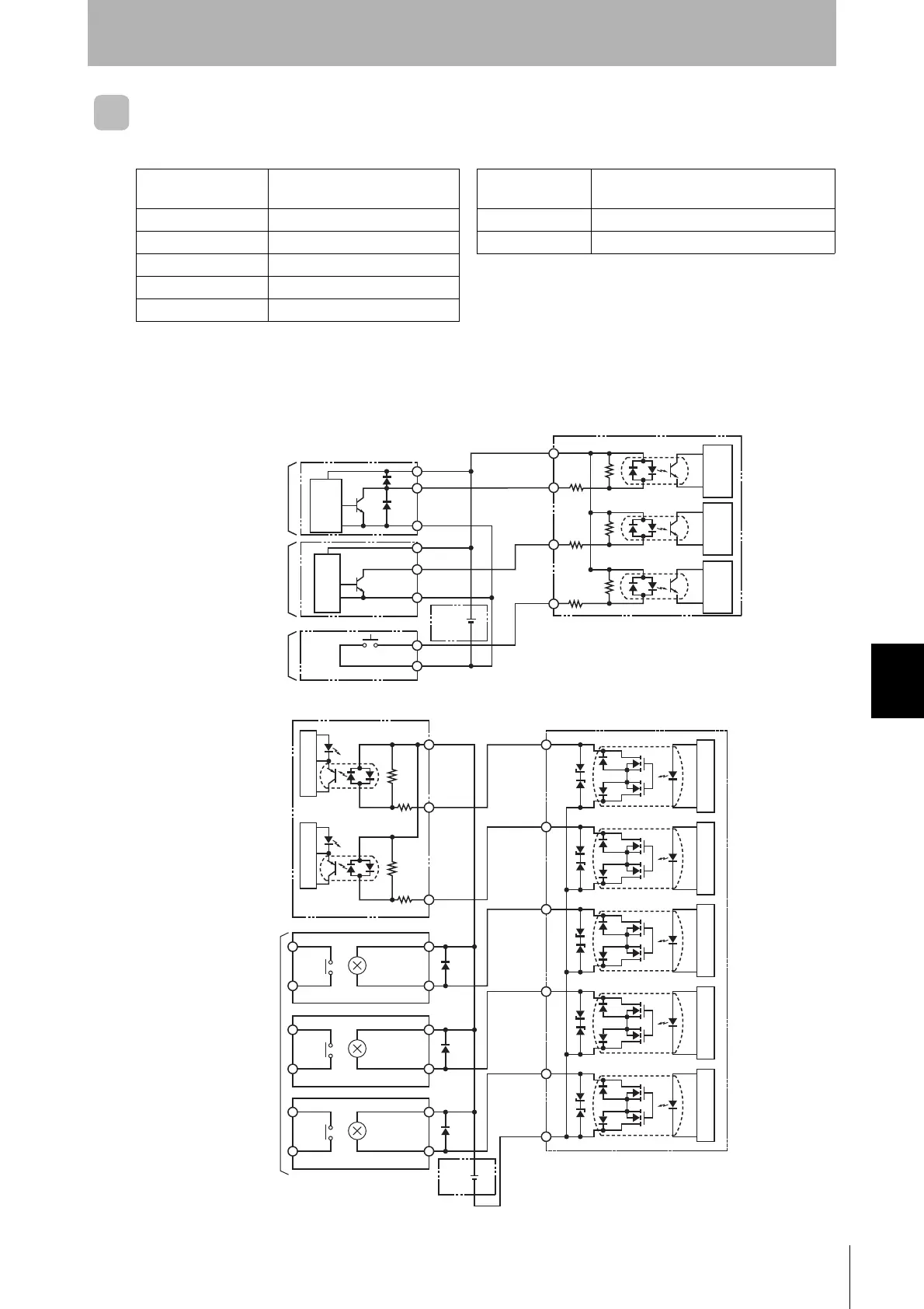
■ I/O Device Wiring Examples
■ Inputs
Outputs
● Input Specifications (RST, TRG/IN1, and TRG/IN2) ● Output Specifications (RUN, BUSY, ERROR, OUT1, and
OUT2)
Input voltage 24 VDC +10% (including ripple)/
15% (PNP or NPN)
Maximum switch-
ing capacity
24 VDC +10% (including ripple)/15%
100 mA photo MOS outputs (PNP or NPN)
Input impedance 2.2 k Leakage current 100 mA max.
Input current 10 mA typical (24 VDC) Residual voltage 2.0 V max.
ON voltage 19 V max. Note 1: The CPU will stop operation and the RST indicator will
light when the RST input is turned ON.
OFF voltage 5 V max.
I/O response time 70 ms max. 2: The transistor may be damaged if an output is shorted
with no load connected.
● PLC Output Unit
● NPN Transistor
Open-collector Output
(e.g., from a 3-wire Sensor)
● Device with contact
(e.g., pushbutton switch)
(e.g., C200H-OD21
or C500-OD412)
+V
OUT
0 V(COM)
+V
0 V
Outputs
RST
TRG1/IN1
TRG2/IN2
ID Controller Input Section
COM_I
2.2 kΩ
2.2 kΩ
2.2 kΩ
Internal
circuits
Sensor internal
circuits
24-VDC
power
supply
Internal
circuits
Internal
circuits
Internal
circuits
● Relay
COM
IN
IN
RUN
BUSY
ERROR
OUT1
OUT2
ID Controller Output Section
COM_O
● PLC Input Unit
(e.g., C200H-ID212 or
C500-ID218)
Internal circuits
24-VDC
power
supply
Internal circuits
Internal circuits
Internal circuitsInternal circuitsInternal circuits
Internal circuits

 Loading...


