15
RFID System
Operation Manual
Section 1 Names and Functions of Components
Section 1
Product Overview
■ Main Display Indicators
■ Head Operation Indicators
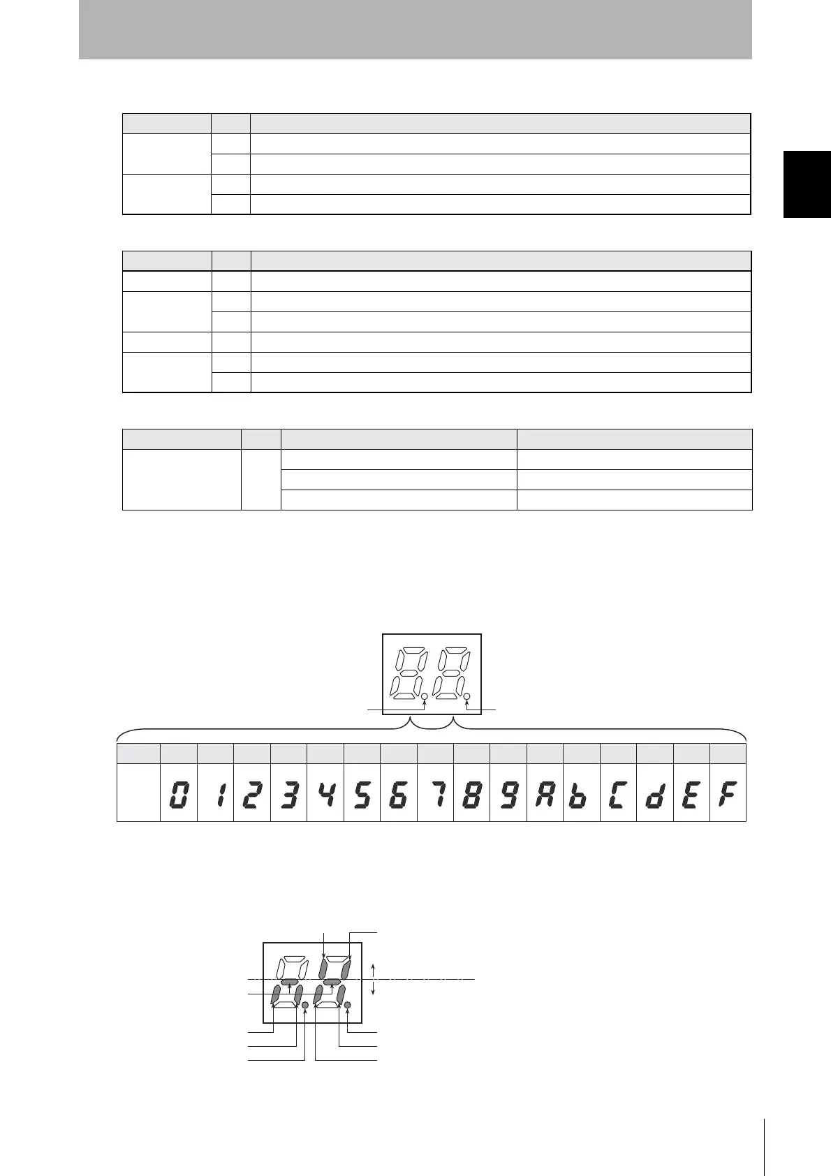
■ Monitor Display
■ End Code Display Mode (Pin 3 of SW4 Turned OFF)
The end code for command processing is displayed. End codes are displayed with two hexadecimal
digits, as shown below.
For normal responses or warning responses, the display lights. For error responses, the display
flashes.
■
I/O Display Mode (Pin 3 of SW4 Turned ON)
The monitor display will show the ON/OFF status of the I/O terminals or the error status.
The segments will be light when the I/O is ON and not lit when the I/O is OFF, as shown below. Error
displays will light when the error occurs and then go out after a short period of time.
Name Color Description
RUN/RST Green Lit when the ID Controller is operating normally.
Red Lit when the external reset input is received.
COMM Green Lit when communicating normally with the host device.
Red Lit when an error is detected in communications with the host device.
Name Color Description
COMM1 Yellow Lit when a communications command for a Data Carrier is being processes for Read/Write Head 1.
NORM1/ERR1 Green Lights once at a normal end to processing for Read/Write Head 1.
Red Lights once at an error end to processing for Read/Write Head 1.
COMM2 Yellow Lit when a communications command for a Data Carrier is being processes for Read/Write Head 2.
NORM2/ERR2 Green Lights once at the end of normal processing for Read/Write Head 2.
Red Lights once at an error end to processing for Read/Write Head 2.
Name Color Mode Description
7-segment display
(2 digits)
Red RUN mode, end code display The end code is displayed.
RUN mode, I/O display User I/O status is displayed.
MAINTENANCE mode The end code is displayed.
Hex 0 1 2 3 4 5 6 7 8 9 A B C D E F
Display
Channel 1 communications indicator
Channel 2 communications indicator
RUN
TRG/IN1
TRG/IN2
BUSY
ERROR
Channel 1 error indicator
Channel 2 error indicator
OUT2
OUT1
Input status indications
Output status indications

 Loading...


