25
RFID System
Operation Manual
Section 2 Wiring
Section 2
Installation and Wiring
Input and Output Lines
■ RESET Signal Input Precautions
• Make sure that the input voltage of the RESET signal does not exceed the maximum voltage (26.4 V).
If the maximum voltage is exceeded, the ID Controller may malfunction.
• To improve the noise immunity, separate the wiring of the input lines from high-voltage equipment or
power lines by at least 1 m.
■ Error Signal Input Precautions
• The maximum switching capacity of the output terminals is 100 mA at 24 VDC (+10%/15%).
If a voltage or load that exceeds the maximum switching capacity is used, the ID Controller may
malfunction.
• Use an auxiliary relay (100 mA max. at 24 VDC) in the output circuit.
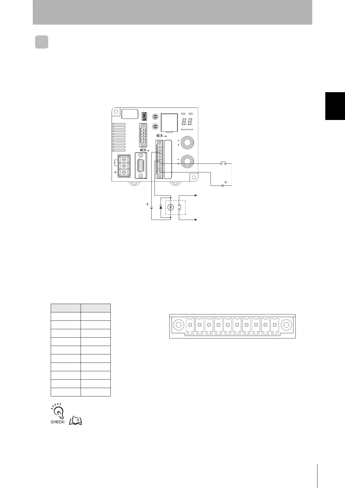
■ Pin Arrangement
Refer to External I/O Port for more information on the external I/O port.
p.13
Pin No. Name
1RUN
2BUSY
3ERROR
4OUT1
5OUT2
6COM_O
7RST
8 TRG/IN1
9 TRG/IN2
10 COM_I
RESET input
24 VDC
24 VDC
To ERROR output
Te rm in al
No.
123 4 5 6 78 910
• Controller Terminal Arrangement

 Loading...


