Important: Units built beiore June 1962
had no
valve
seals.
2.
OU the stem of
each
valve
lightly
and insert
each
in
its
own guide.
3. Check
each
valve for a
tight
seat
with
an air
pressure
type
tester
If a
tester
is not available, make pencil
marks at intervals on the valve face and
observe
if the
marks rub off
uniformly
when the valve is rotated part
of
a turn in the
seat.
If the
seat
is not tight, regrind
the valves.
4.
Using a valve spring
compressor,
compress
each
valve
spring
and insert the valve spring retainer, and retainer
locks.
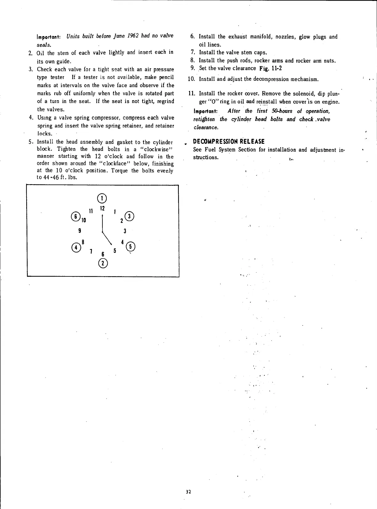
5. Install the
head
assembly and
gasket
to the cylinder
block.
Tighten the
head
bolts in a "clockwise"
manner starting
with
12 o'clock and
follow
in the
order shown around the "clockface" below,
finishing
at the 10 o'clock position. Torque the bolts evenly
to
44-46
ft.
lbs.
6. Install the
exhaust
manifold, nozzles, glow plugs and
oil
lines.
7. Install the valve stem
caps.
8. Install the push rods, rocker
arms
and rocker arm nuts.
9. Set the valve
clearance
Fig. 11-2
10.
Install and adjust the decompression mechanism.
11.
Install the rocker cover. Remove the solenoid, dip plun-
ger "0"
ring
in
oil
and reinstall when cover is on engine.
Important: Aiter
the
first 50-hours
ol
operation,
retighten
the
cylinder head bolts
and
check .valve
clearance.
,
DECOMPRESSION
RELEASE
See Fuel System Section for installation and adjustment in-
structions.
32
 Loading...


