10 OPAL-RT Technologies OP4200 User Manual
OP4200 Hardware
Hardware Interface
HARDWARE INTERFACE
Side Connectors
B C D E G HF
A
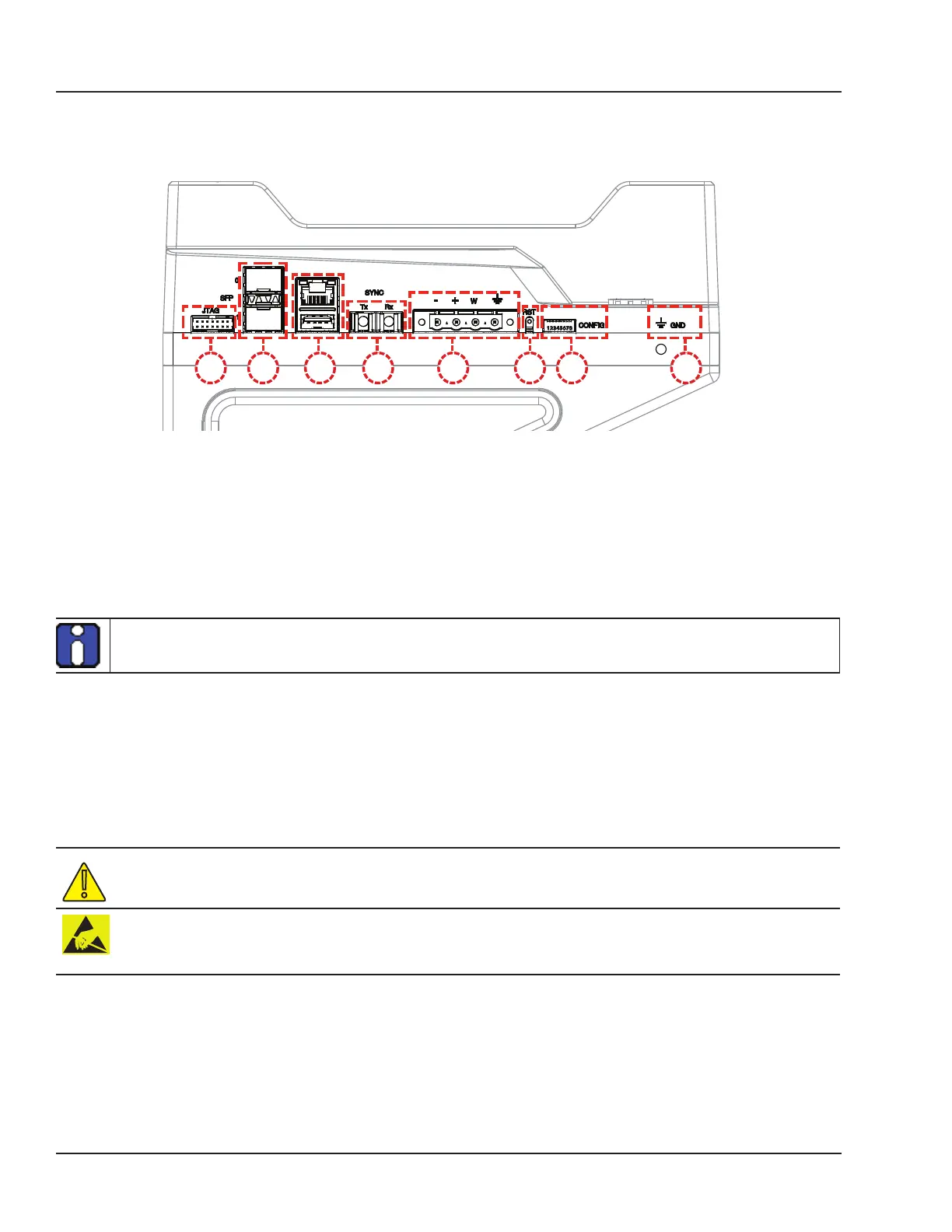
Figure 1: OP4200 side connector panel
A. JTAG connector for ZYNQ programming (used in the event of lost or damaged configuration, this
feature should only be used by qualified personnel).
B. SFP (small form-factor pluggable) ports controlled from the FPGA, for high-speed communication
with other simulator FPGAs or with third-party devices (see
“CONNECTIVITY” for details). Each
socket controls one communication link. SFP transceivers and fiber optic cables must be selected
according to the type and speed of the communication protocol implemented in the FPGA (OPAL-
RT MUSE link or 3rd-party device connection).
MUSE link requires specific SFP and cable:
SFP: Avago AFBR-57R5APZ
Cable: LC-LC multimode 850nm optical fiber
C. RJ45 (network connection) and USB 2.0 connector.
D. Fiber optic connectors (Rx and Tx), used to synchronize the OP4200 with other simulators.
E. Phoenix terminal power connector. Can be used with OP5972 power jack adapter kit.
F. Reset button
G. DIP switches: the position of the boot mode switches allow selection of different boot modes for the
processor. (see
“DIP Switch Configurations” for detailed information)
H. Ground connector screw: attach grounding wire to nearest ground when using OP4200 in high risk
environments.
The OP4200 may be subject to EMI when installed in proximity to other devices
OPAL-RT strongly recommends the use of anti-static wrist straps whenever handling any electronic
device provided by OPAL-RT. Damage resulting from electrostatic charges will not be covered by the
manufacturer’s warranty.