OP4200 User Manual OPAL-RT Technologies 29
OP4260-1 32 DIGITAL OUTPUTS
OP4260-1 32 DIGITAL OUTPUTS
The OP4260-1 provides 32 push-pull digital outputs divided in two banks of 16. Each bank can be
separately powered by the user. The board can accept up to 30Vdc and can sink or source 50 mA dc
(recommended) with no trip action.
Higher currents will trip the current protection and all the output levels provided in this
datasheet will not be applicable
FEATURES
• 32 Dout push-pull
• Wide operating voltage range: Vuser 5 Vdc to max 30 Vdc
• Load current up to 50 mA DC per output
• O/V and reverse voltage supply protection
• Short-circuit current limitation
• Operating frequency DC-500Khz
• Low ON/OFF time propagation delay: ≤ 200ns @ 25°C at 5 V
• Low ON/OFF time propagation delay: ≤ 65ns @ 25°C from 15 to 30 V (optional)
• Outputs are tri-stated.
• Outputs may be connected in parallel for higher (2 times) current capability: use matched pair
(example: DOUT_0 with 1 , DOUT_2 with 3, etc.)
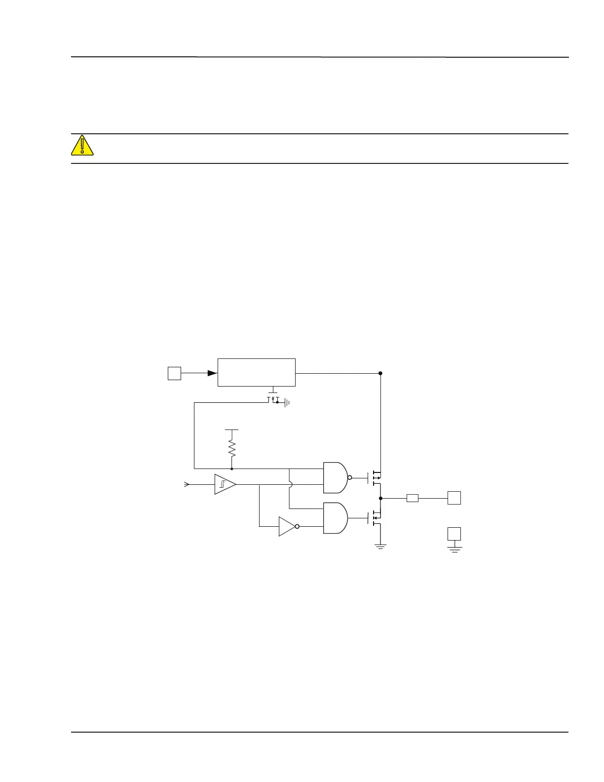
DOUT
GND-ISO
SC Protection
User supply
Supply protections
Over Voltage
Reverse Voltage
IN
From Simulator
V
CC
GND-ISO
GND-ISO
ENA
FAULT
Figure 21: OP4260-1 block diagram
Recommendations
Users should adjust the power supply level (through the DB37 connector) to get the proper high
voltage level at the DOUT.
Use a proper damping circuit, (a serial resistor capacitor circuit tied to the GND as close as possible
to the user Device Under Test) to minimize ringing and over/undershoot according to the connection
length (from OP4260-1 to user device).
The following parameters are a good starting point for the RC values: R=150Ω , C = 100pF. Tuning is
necessary, according to application parameters.