12 OPAL-RT Technologies OP4200 User Manual
OP4200 Hardware
Cassettes
CASSETTES
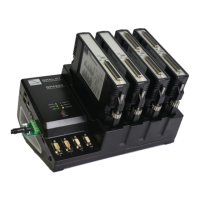
There are 4 cassettes slots, labeled 1 to 4, in the OP4200. The OP4200 standard configuration includes
the following four cassettes:
Slot 1: OP4240-1, 16 analog inputs
Slot 2: OP4230-1, 16 analog outputs
Slot 3: OP4250-1, 32 digital inputs
Slot 4: OP4260-1, 32 digital outputs.
See the sections specific to each cassette for conditioning details.
Digital cassettes have two DB37 connectors (one for channels 00-15 and one for channels 16-31), and
analog cassettes have one DB37 connector (for channels 00-15).
Cassette LEDs
Each cassette has 4 LEDs, each used to indicate a specific status:
LED # NAME DESCRIPTION
1
Status Blinking green: FPGA and hardware functioning normally.
Blinking red: FPGA not responding, not sending heartbeat signal to cassette.
Off: hardware malfunction in cassette.
2
VUser1
(digital only)
Green = external Vuser present
Red = no external Vuser present
3
VUser2
(digital only)
Green = Vuser present
Red = no Vuser present
4
User NOT USED