OP4200 User Manual OPAL-RT Technologies 19
OP4200 Hardware
Initial Setup
Testing Signals Using the Loopback Kit
NOTE
The following procedure is only used for test purposes when no external source is available.
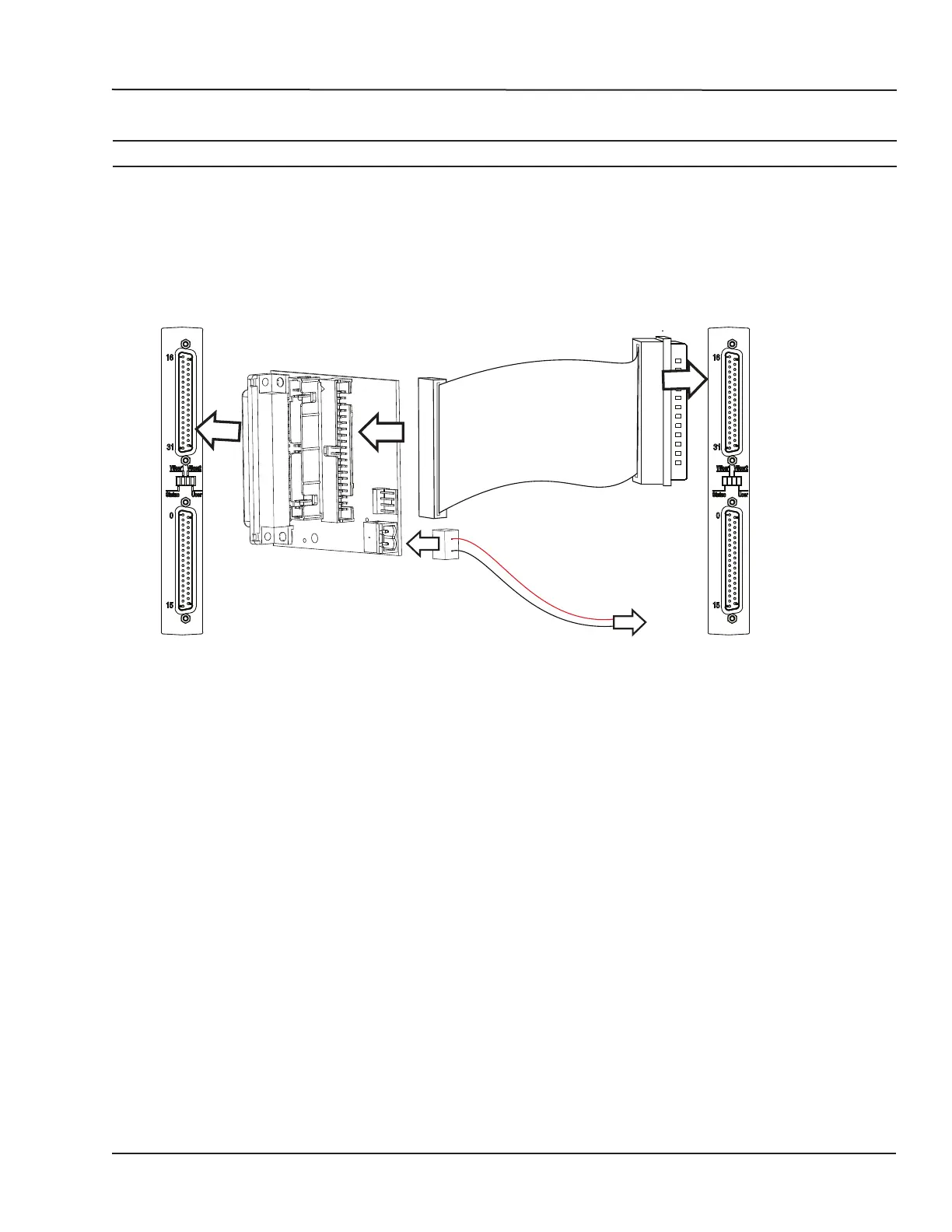
The loopback kit included in the starter kit allows users to test system signals. Connection is made easy
with a custom flat cable that matches OPAL-RT standard DB37 pin assignments.
The loopback kit allows users to test signals by connecting the output cassette to the input cassette. If
the input reads each output signal, the unit is functioning properly and is ready to be put into service.
OUTPUT
CASSETTE
LOOPBACK BOARD
INPUT
CASSETTE
To external
source
Figure 13: Connecting the loopback kit
1. Connect one end of the flat cable to the loopback board
2. Connect the loopback board to the OP4200 DB37 output cassette
3. Connect the other end (DB37 connector) of the flat cable to the OP4200 DB37 input cassette
4. When this kit is used to test digital signals, connect the Vuser (required to preserve isolation) from
the loopback board (connector end) to an external source (wire end).