OP4200 User Manual OPAL-RT Technologies 11
OP4200 Hardware
Front Connectors
FRONT CONNECTORS
B C D
A
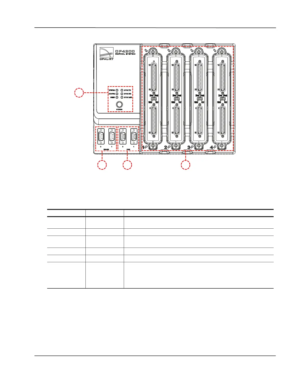
Figure 2: OP4200 rear connector panels
A. Function LEDs and Power button
Press the power once to power up the unit. Press twice to shut down. The power button lights when
the unit is powered up and functioning.
There are 6 LED indicators on the housing:
NAME Color Description
STATUS Green
Yellow
Indicates that the unit is powered up and functioning properly
Indicates a system error
CONFIG Green Indicates that FPGA programming is complete.
USER Green
Yellow
User configurable to display a condition specified by the user. If undefined,
displays no status.
SYNC TX Green Lights to indicate when unit transmits a synchronization signal.
SYNC RX Green Lights to indicate when unit receives a synchronization signal.
SYNC M/S* Green
Yellow
Lights yellow (at startup) when no model is loaded. Once a model is loaded:
Indicates that the unit is in Master mode.
Indicates that the unit is in Slave mode mode (the “Use external
synchronization source” checkbox in OPAL-RT Board driver via allows the
user to make the unit a slave)
B. RS232 connectors. Allow a direct connection to the host computer to display the “OP4200 System
Configuration” IP address modification interface.
C. CAN connectors: CAN 2.0A, 2.0B, and ISO 118981-1 standard compliant
D. I/O cassettes (see “Cassettes” for more details).