Wiring
- 25 -
optek-Manual--1004-1022-02--156-US-2017-12-11
www.optek.com
8.5 Connecting the relay outputs
Danger!
Electrical voltage!
Switch the converter voltage-free before connecting!
Install electrical connections only by qualified electricians!
Tool • Screw driver
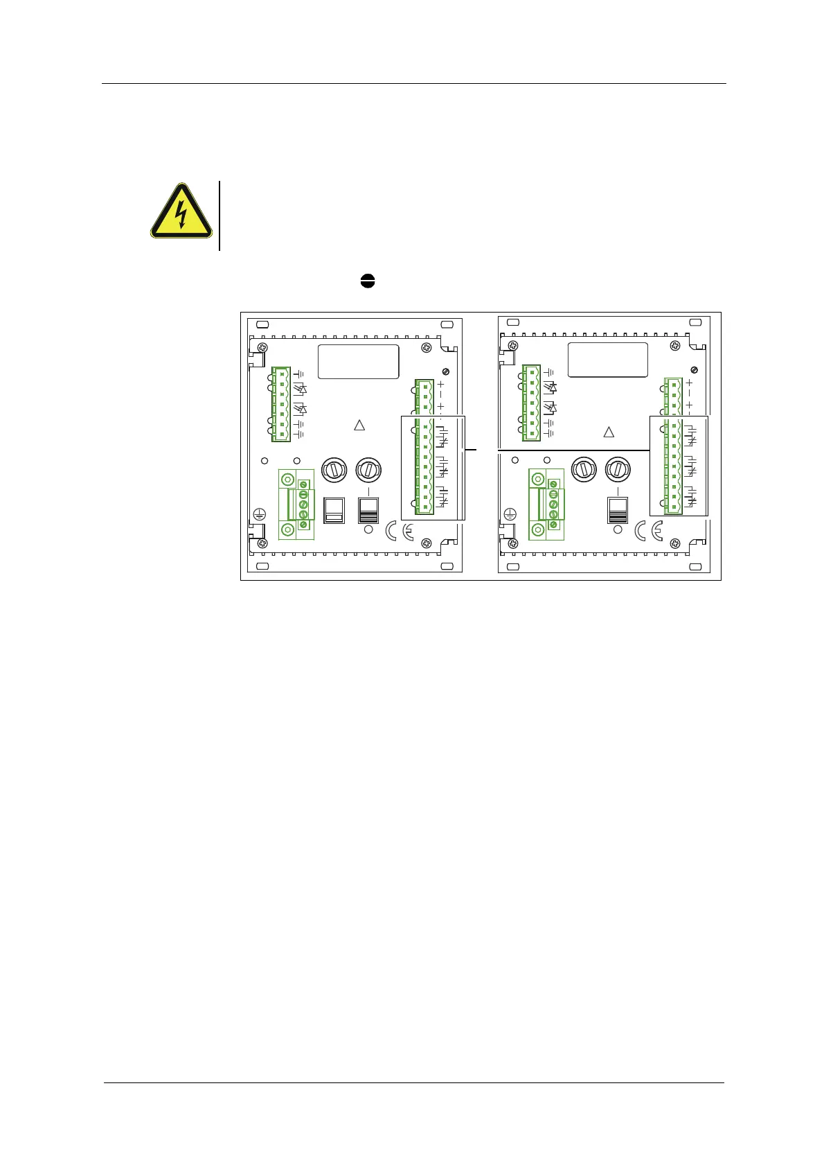
Fig. 16 Relay outputs
The converter is equipped with three relay outputs (30):
• Relay output 1 terminals 10 / 11 / 12
• Relay output 2 terminals 13 / 14 / 15
• Relay output 3 terminals 16 / 17 / 18
Relay output 1 may be assigned a limit value for alarm I, while relay output 2 may
be assigned a limit value for alarm II. Relay output 3 is assigned a minimum
value for indication of a lamp failure at the sensor.
The lamp failure relay is operated enabled, i. e. the relay is picked up in normal
operational state. If the lamp current falls below the minimum value of approx.
310 mA, the lamp failure relay is disabled. If the corresponding request is given,
this allows monitoring regarding lamp and power failure.
ALARM II
14
MADE IN GERMANY
OPTEK-DANULAT
N
PE
L
230V
LAMP AL
17
18
15
16
3
DETECTORINPUTS
5
5
4
50/60Hz, 30VA
230VAC, T0,315A
115VAC, T0,630A
115/230V
!
5
1
2
8
ALARM I
11
13
12
10
9
mA
VOLTAGE
6
7
LAMP
LAMP -
212019
ALARM II
14
OPTEK-DANULAT
MADE IN GERMANY
N
PE
L
LAMP AL
17
18
15
16
1
2
5
5
4
5
3
DETECTORINPUTS
8
!
24V DC
50/60Hz, 30VA
24V, T1,25A
ALARM I
11
12
13
9
10
mA
VOLTAGE
6
7
LAMP
LAMP -
212019