Commissioning
- 31 -
optek-Manual--1004-1022-02--156-US-2017-12-11
www.optek.com
9.4 Setting the zero point
During commissioning, and routine checks, after lamp change or maintenance,
always check the system zero point. To check or set the system zero point
correctly, proceed as follows:
• Clean the windows of the armature or the probe.
• Fill the armature with clean, particle-free water or dip the stick sensor into
clean, particle-free water.
• There must not be any gas bubbles in the medium.
• Remove gas bubbles from the windows.
• Cover the armature so as to prevent direct sunlight from penetrating.
• Let the system work for at least 15 minutes before checking the system
zero point.
Tool • Screw driver
1. Loosen the measuring range plate on the front at both screws.
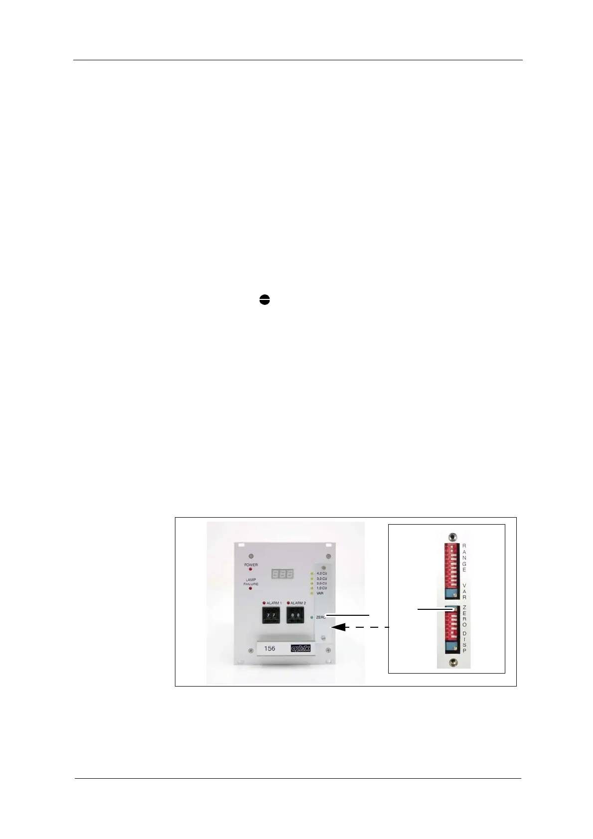
2. Use a screw driver to turn the potentiometer (12) clockwise until a measured
value is displayed, then turn it slowly anticlockwise to the left.
• When reaching the zero point, the green "ZERO" LED (5) lights up. As
long as this LED lights up, the zero point is set to + 1 % of the current
measuring range.
If the zero point may not be set, first check sensor contents, windows, lamp and
wiring as well as the sensor and the converter serial number and after that
repeat the procedure.
After changing the detector module and / or the optical path length, in very rare
cases, the zero point may only be set after adjusting the internal operating ran-
ge.
Fig. 21 Potentiometer for zero point setting