Commissioning
- 36 -
optek-Manual--1004-1022-02--156-US-2017-12-11
www.optek.com
9.7 Adjusting the digital read-out
Tool • Screw driver
1. Loosen the measuring range plate on the front at both screws.
2. According to the following table, switch the DIP switches 5 and 6 (13) to ON
position (left) or OFF position (right).
Note!
DIP switches 1 to 4 are used for zero point factory setting.
Proceed as follows to set the end value of the digital read-out:
1. Fill the armature with a slightly hazy liquid or dip the probe into a slightly hazy
liquid. You may as well cover the light beam - if the sensor assembly is not
yet installed - so that a stable measuring result is obtained within the set
measuring range.
2. Connect a multimeter to terminals 8 and 9 on the back of the converter. It
displays the corresponding measuring result in mA.
• mA values mean the following: 4 mA = 0 % and 20 mA = 100 %
3. Use a screw driver to set the desired end value of the digital read-out at the
potentiometer (14) turning. Proceed according to this example:
• mA display = 14.4 mA correspond to a display of 65 %
• Adjust the digital read-out to 065. This corresponds to a display from
0 to 100.
• Adjust the digital read-out to 325. This corresponds to a display from
0 to 500.
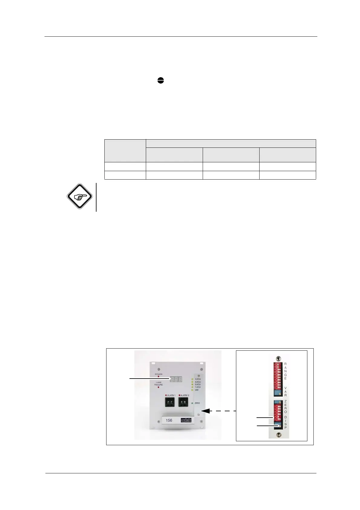
Fig. 24 Potentiometer for digital read-out adjustment
Tab. 6 DIP switch positions
DIP switch Setting of the decimal place in the digital read-out
No decimal place
XXX
1 decimal place
XX.X
2 decimal places
X.XX
5 OFF ON OFF
6OFF OFF ON