Wiring
- 21 -
optek-Manual--1004-1022-02--156-US-2017-12-11
www.optek.com
8.4 Connecting the sensor
Danger!
Electrical voltage!
Switch the converter voltage-free before connecting the sensor!
Install electrical connections only by qualified electricians!
Connection to the
converter
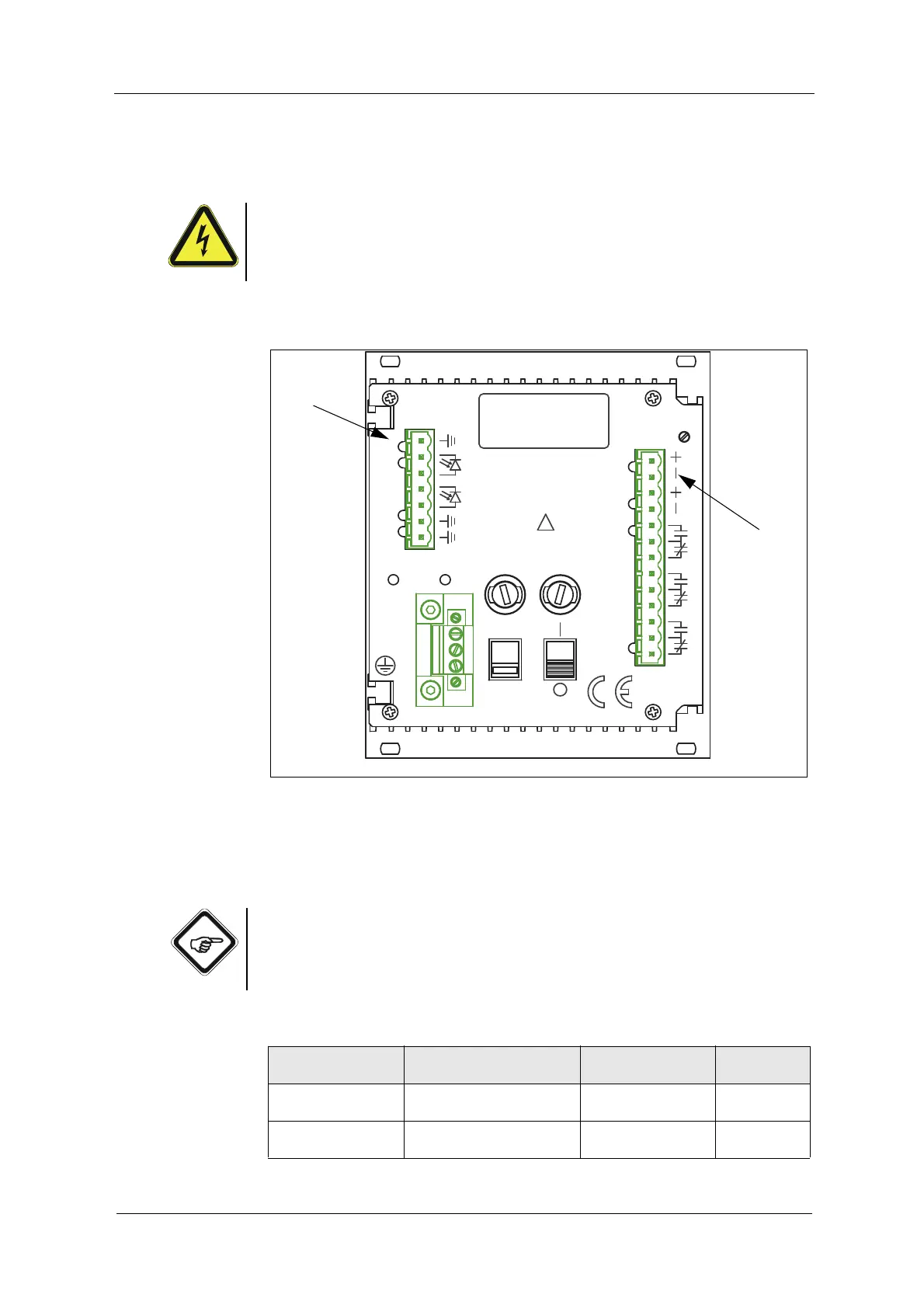
The following connections are on the back of the converter:
Fig. 13 Detector inputs and lamp outputs of the converter 156
Letters stand for
• G Detector inputs (5, 1, 2)
• H Lamp outputs (6, 7)
Note!
Stick to the detector inputs and lamp outputs specified in table 2. Thus, danger
of mixing inputs and outputs up is minimized. Detector inputs 3, 4 and 2 x 5 are
not used. The detector input (5, 4, 3) is inactive.
Tab. 2 Connections
Number of sensors
Sensor type
Detector input connection
of the converter
Lamp output
Cable set
lengths max.
1 sensor
AF56
Detector input (5, 1, 2) Lamp output (6, 7) 100 m / 328 ft.
1 sensor
AS56
Detector input (5, 1, 2) Lamp output (6, 7) 50 m / 164 ft.
ALARM II
14
MADE IN GERMANY
OPTEK-DANULAT
N
PE
L
230V
LAMP AL
17
18
15
16
3
DETECTORINPUTS
5
5
4
50/60Hz, 30VA
230VAC, T0,315A
115VAC, T0,630A
115/230V
!
5
1
2
8
ALARM I
11
13
12
10
9
mA
VOLTAGE
6
7
LAMP
LAMP -
212019