Description of the converter
- 8 -
optek-Manual--1004-1022-02--156-US-2017-12-11
www.optek.com
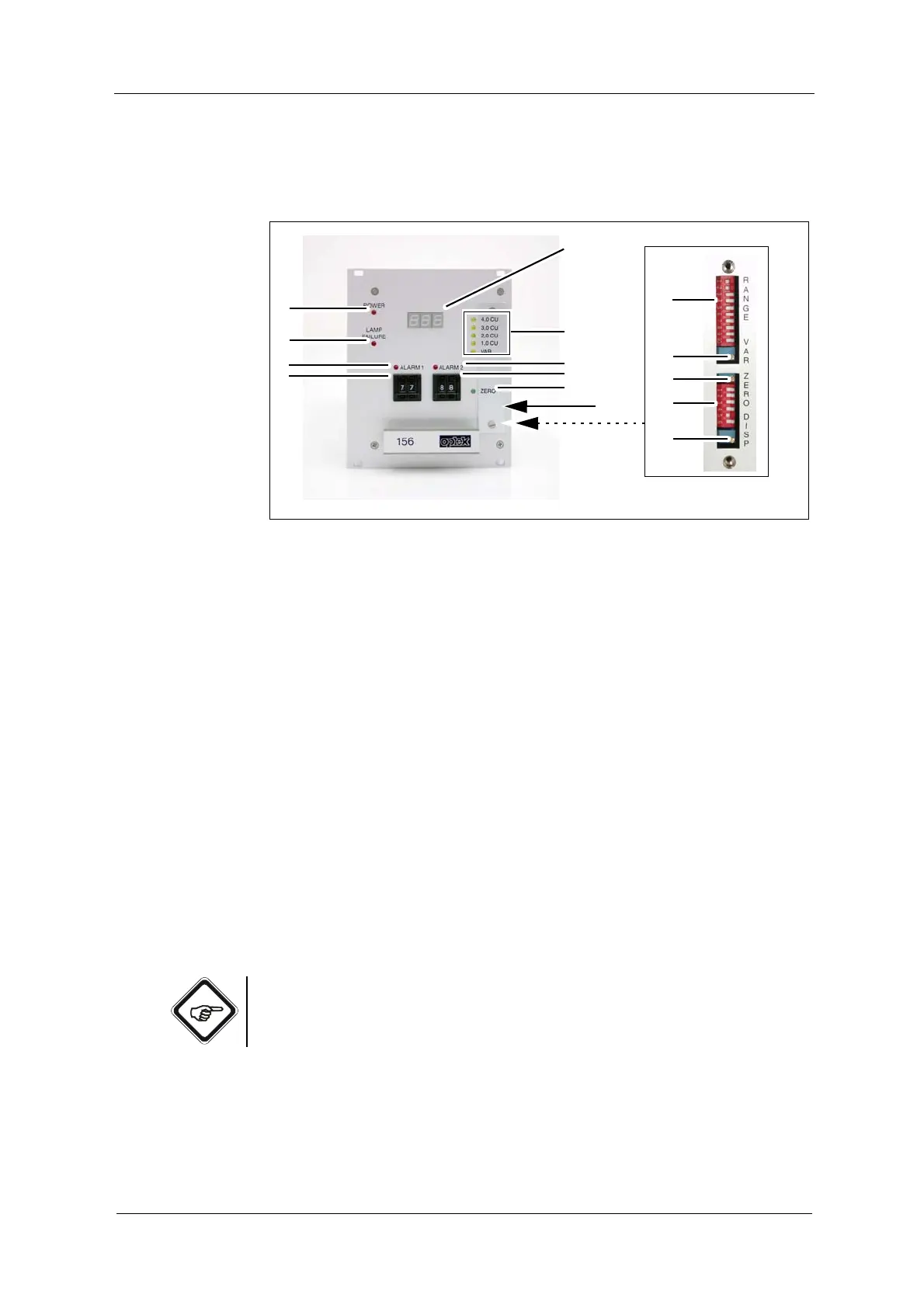
5.1 Converter front view
Fig. 2 156 converter
Numbers stand for:
1. Digital read-out, LED display, 3 digits, height: 7 mm
2. 5 LEDs (yellow), indication of set measuring range
3. LED (red), switch indicator for alarm 2
4. Encoding button for setting alarm 2 in steps of 1 % of the respective
measuring range
5. LED (green), zero point indication
6. Encoding button for setting alarm 1 in steps of 1 % of the respective
measuring range
7. LED (red), switch indicator for alarm 1
8. LED (red), lamp failure indication
9. LED (red), power indication
10. DIP switch (RANGE 1 - 10) for measuring range setting
11. Potentiometer (VAR) for setting the variable measuring range
12. Potentiometer (ZERO) for zero point setting
13. DIP switch (DISP 5 - 6) for setting digital read-out 1
14. Potentiometer for setting digital read-out 1
15. Measuring range plate for CU
Note!
DIP switches DISP 1 - 4 (position 13 in fig. 2) only serve for factory calibration
and may not be actuated by the user.