Commissioning
- 33 -
optek-Manual--1004-1022-02--156-US-2017-12-11
www.optek.com
Tool • Screw driver
1. Loosen the measuring range plate on the front at both screws.
2. According to the following table, switch the DIP switches to ON position (left)
or OFF position (right).
First, set the largest possible measuring range (4 CU) to get an overview of
possible measuring results.
3. Select the measuring range where none of the measuring results exceeds
the measuring range.
Example:
highest measuring result: 1.8 CU = measuring range to select: 0 - 2 CU
This can be easily checked via the mA-output or by increasing an alarm in
the widest measuring range until the alarm LED goes off.
Note!
For special uses, the variable measuring range may be set to a customized
measuring span. The value may range between 0.5 and 4 CU. At delivery, the
factory setting of this measuring range is 0.5 CU.
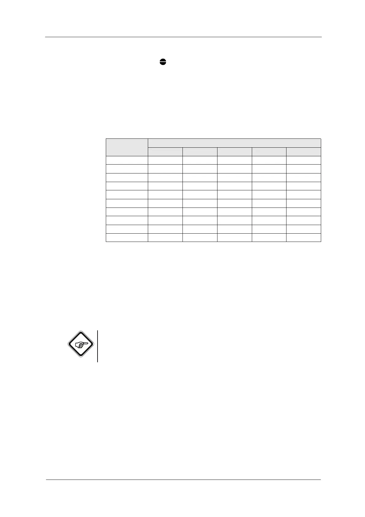
Tab. 5 DIP switch positions
DIP switch Measuring range:
0 - 4 CU 0 - 3 CU 0 - 2 CU 0 - 1 CU Variable
1 ON OFF OFF OFF OFF
2 ON OFF OFF OFF OFF
3OFFON OFF OFF OFF
4OFFON OFF OFF OFF
5OFFOFFON OFF OFF
6OFFOFFON OFF OFF
7 OFF OFF OFF ON OFF
8 OFF OFF OFF ON OFF
9 OFF OFF OFF OFF ON
10 OFF OFF OFF OFF ON