Version 1.2.8 - 2020-08-03 25Translation of original operating manual
MT50 GB
MT50_GB_3.fm
4.3.2 Load attachment points
The milling-machine can be lift by means of a sling or on the recess in the mounting foot with
the help of a forklift truck.
WARNING!
Check if all clamping screws of the spindle head carrier are tightened before lifting the
machine.
Raising / lowering the cross table on page 37
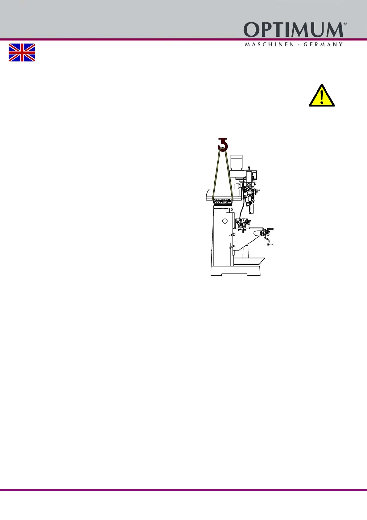
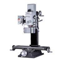
Alternatively it is possible to lift the milling machine by means of a sling as displayed inAbbil-
dung 4-1.
The cross table has to be completely travelled to
the machine stand.
The spindle head carrier must be positioned as
illustrated.
The four clamping screws (A) of the spindle head-
holder must be tight.
Make sure that the load attachment does not
cause damage to components or paint.
Lift and transport the machine using an appropri-
ate lifting device (crane, etc.).
Total weight on page 19
Img.4-1: Example: Lifting at the spindle head carrier using a sling