-66 -
4.4.3 LT, LTF, MT, F2, F6, G5, G7, P7 models
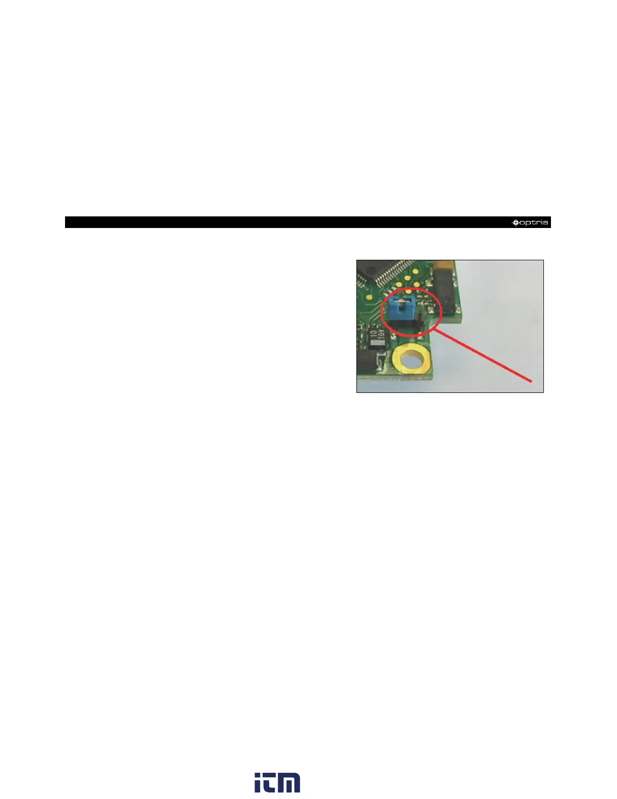
At the bottom side of the mainboard PCB you will find a
connector (jumper) which has been placed from factory
side as shown in the picture [left and middle pin
connected]. In this position the ground connections
(GND power supply/ outputs) are connected with the
ground of the electronics housing.
To avoid ground loops and related signal interferences
in industrial environments it might be necessary to
interrupt this connection. To do this put the jumper in the
other position [middle and right pin connected].
If the thermocouple output is used the connection GND
– housing should be interrupted generally.