Do never connect a supply voltage to the analog outputs as this will destroy the output!
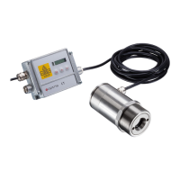
The CTlaser is not a 2-wire sensor!
Use a separate, stabilized power supply unit with an output voltage in the range of 8–36 VDC
(CTlaser 4M: 8–30 VDC) which can supply 160 mA. The residual ripple should be max 200 mV.
For all power and data lines use shielded cables only. The sensor shield has to be grounded.
The cable gland M12x1.5 allows the use of cables with a diameter of 3 to 5 mm.
1. Remove the isolation from the cable (40 mm power supply, 50 mm signal outputs, 60 mm functional
inputs), cut the shield down to approximately 5 mm and spread the strands out.
2. Extract about 4 mm of the wire isolation and tin the wire ends. Place the pressing screw, the rubber
washer and the metal washers of the cable gland one after the other onto the prepared cable end
(see Figure 17).
w ww. . com
information@itm.com1.800.561.8187