Hardware Overviews
Figure Legend
4 PSU 1 AC inlet 5 System status indicator panel 6 PCIe card slots 1-6
7 Network (NET) 10 GbE ports: NET0–
NET3
8 USB 2.0 connectors (2) 9 PCIe card slots 7–11
10 Service processor (SP) network
management (NET MGT) port
11 Serial management (SER MGT)
RJ-45 port
12 DB-15 video port
■
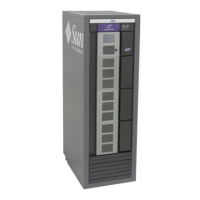
Ethernet Ports - The ZS4-4 has four RJ-45 10-Gigabit Ethernet (10GbE) network
connectors on the rear panel, labeled NET 0, NET 1, NET 2, and NET 3 (bottom left to
top right), as shown in the following figure. Use these ports to connect the appliance to the
network.
The LEDs located above the NET ports, labeled 2, 0, 3, 1 (left to right) are Link/Activity
indicators.
LED Status
OFF (1) No Link
ON (0) Link and no activity
Blink Link and activity
Note - Speed is not indicated for the NET ports.
■
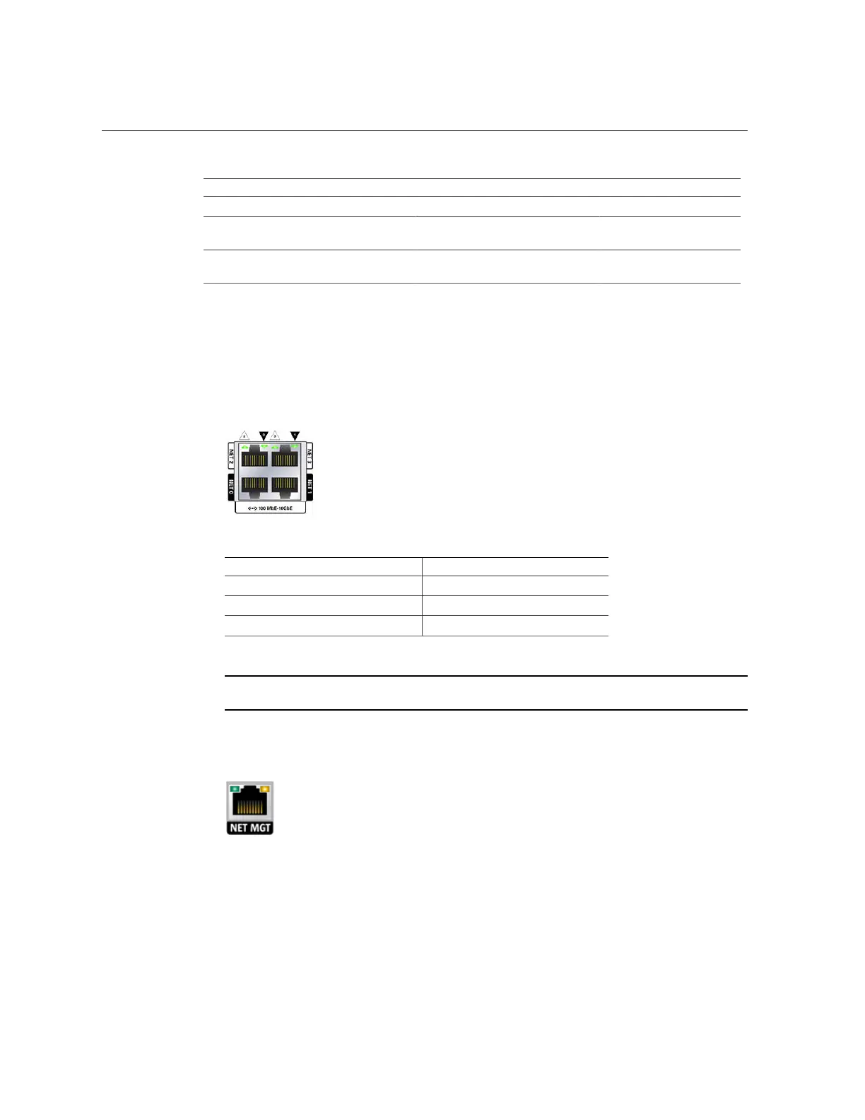
Network Management Port - The network management connector (NET MGT), shown
in the following figure, is an RJ-45 port and provides an alternate terminal interface to the
service processor (SP) console.
■
Serial Management Port - The serial management connector (SER MGT), shown in the
following figure, is an RJ-45 port and provides a terminal connection to the SP console.
Installation Prerequisites and Hardware Overviews 33

 Loading...