3600 Analyzer for O
2
Measurement—Operator’s Manual 45
3600O2.OM.E9903
Requirements for these user-supplied cables are in section 2.1.5, User-supplied
Cabling Requirements—note that you must ground each cable shield properly to
assure proper operation.
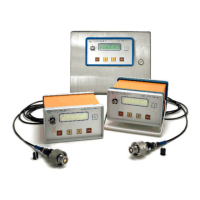
3600/3600M indicating instrument rear panel, panel or 19" rack mount version, shown
with optional external pressure sensor input
To make any of these connections, you must remove the rear instrument panel.
First, make sure the power supply is unplugged, and remove the front-panel key.
Then place the instrument face-down and loosen the four 3-mm Allen-head
screws. Carefully pull off the rear panel, taking care not to disconnect any wires, to
expose the terminal strip wiring diagram label.
The model 3600 and the model 3600M series have different terminal strip wiring
connections. A wiring label inside the rear panel identifies each unit’s terminal
strip connections. Each of the following wiring descriptions identifies the
appropriate terminal connections of each model.
3600 series
wiring label:
3600 series
terminal strip:
 Loading...