6 3600 Analyzer for O
2
Measurement—Operator’s Manual
3600O2.OM.E9903
1.2 What to check before using the system
Before making initial measurements, first:
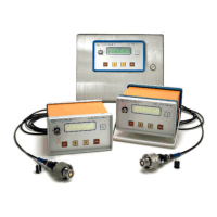
Check the voltage and line power—The indicating instrument is available in
115 VAC, 230 VAC, and 10–30 VDC versions. A sticker on the rear panel indicates
which voltage you have. Make sure that it is correct before connecting to a power
supply. Make sure that the ground of the AC supply is connected.
The DC connection must be made by the user, as described in section 2.1.
Note that the portable version can operate without connection to an external
power supply for a period up to 16 hours. If your instrument periodically displays
a “LOW BATTERY” message, it is necessary to recharge the batteries by plugging
the instrument into a power supply and leaving it plugged in overnight.
Check instrument mounting—The instrument is available in portable, process
(panel or 19" rack mount), or wall mount versions. If you are still configuring your
installation, refer to section 2.1 for relevant mounting information.
Check instrument connections—The instrument includes connections for line
power, the oxygen sensor, and an optional external pressure sensor. In addition,
the output pack (optional on portable instruments) includes alarm outputs, analog
current outputs, and an RS-232 serial output. Refer to section 2.1 for complete
wiring and connection information.
Check the oxygen sensor—Shipping conditions can adversely affect Orbisphere
oxygen sensors. You should perform a sensor service as described in section 1.5
before trying to make measurements.
However, if you intend to make trial measurements with the sensor as shipped,
first examine the sensor head. To do this, remove the plastic base at the bottom of
the sensor, then unscrew the calibration cap by loosening its collar.
Your sensor head is fitted with a screw-on protection cap. For a view of the sensor
head, you must remove the cap, using the wrench supplied in your recharge kit.
Do this carefully, making sure not to disturb the membrane that covers the sensor
head, held in place by a membrane holding ring.
O
2
sensor components, including exploded view of membrane assembly order