58 3600 Analyzer for O
2
Measurement—Operator’s Manual
3600O2.OM.E9903
2.2.4 Model 32002.x Multiparameter Flow Chamber Installation
This flow chamber accommodates one or two oxygen sensors and one pressure
sensor. Most series 3600 systems will only use one gas sensor; in these instances,
one side of the flow chamber will be shut off with one of the two stainless steel
plugs (model 28123) included.
When mounted, the outlet port should be located at the lowest point to allow
condensation to escape with the outgoing gas. To mount, secure the two threaded
holes at the back of the flow chamber to a vertical surface with the supplied bolts,
so that the pressure sensor and its cable are on top. In this way, the inlet port faces
out, directly opposite the mounting bolts; the outlet port points downward to
permit liquid drainage.
A “Top View” diagram below gives relevant dimensions. Note that a user-supplied
standoff block can be placed between the flow chamber and wall to provide
operators improved access for sensor removal.
Sample lines can be stainless steel, copper, or plastic tubing with low oxygen
permeability, although stainless steel is preferred. When ordered, the flow chamber
must be specified to accommodate either 6-mm or ¼ inch OD tubing.
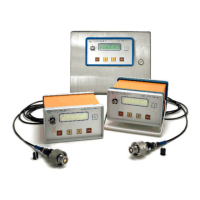
Model 32002.x flow chamber shown with oxygen sensor (right), 28117 external
pressure sensor (center), and optional second oxygen sensor (left)