Appendix G: Installation Checklist
2 Ocean TRx™ 4500 Installation and Operations Manual
Crate Visual Inspection
Please conduct a general visual inspection of each crate, to verify that no external
damage has occurred.
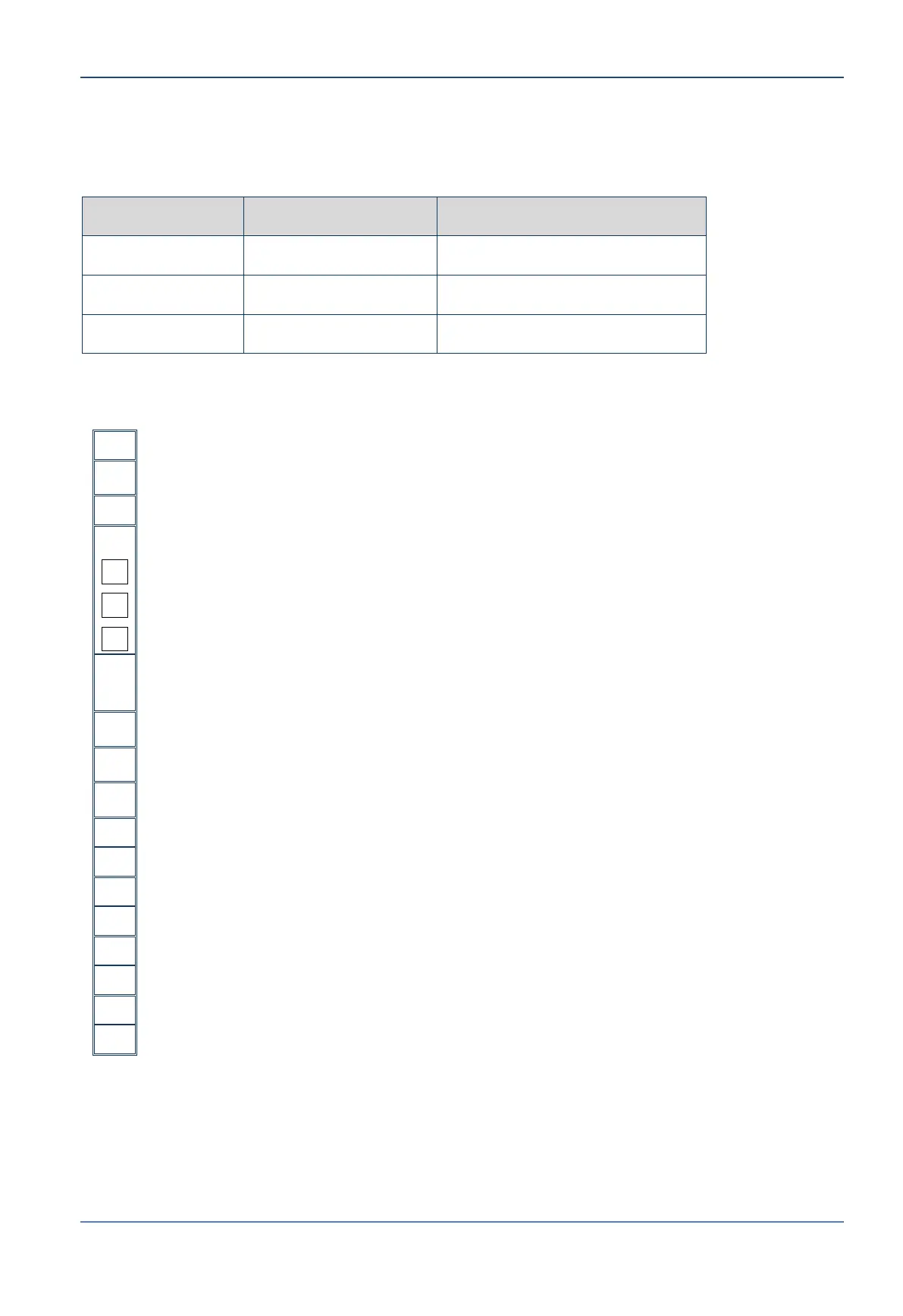
CHECKLIST
System crate is unpacked –4 side walls and top of crate removed
RADOME crate is unpacked –4 side walls and top of crate removed
Tie-wraps removed from RF Feed, Azimuth, Elevation, and Tilt Axes
Stow locks are removed:-
Elevation Axis locking pin
Tilt Axis plugs
Azimuth Axis locking pin
For bottom hatch only: System lifted to a 60cm staging platform or axle
stands for RADOME assembly, using a parallel-strap lifting harness
RADOME assembled according to instructions
System lifted to designated location, using RADOME lifting harness
System mounted on RADOME support using the installation kit
Coaxial cable connected between ADE and BDE
Ship mains power cable connected to ADE
CCU installed in 19’’ rack below deck with supporting rails
If ordered, 1U 17’’ LCD and KBD unit installed below CCU
Ship’s compass connected to CCU
Tx and Rx cables connected between modem and CCU
All other required connections (LAN, NMS)