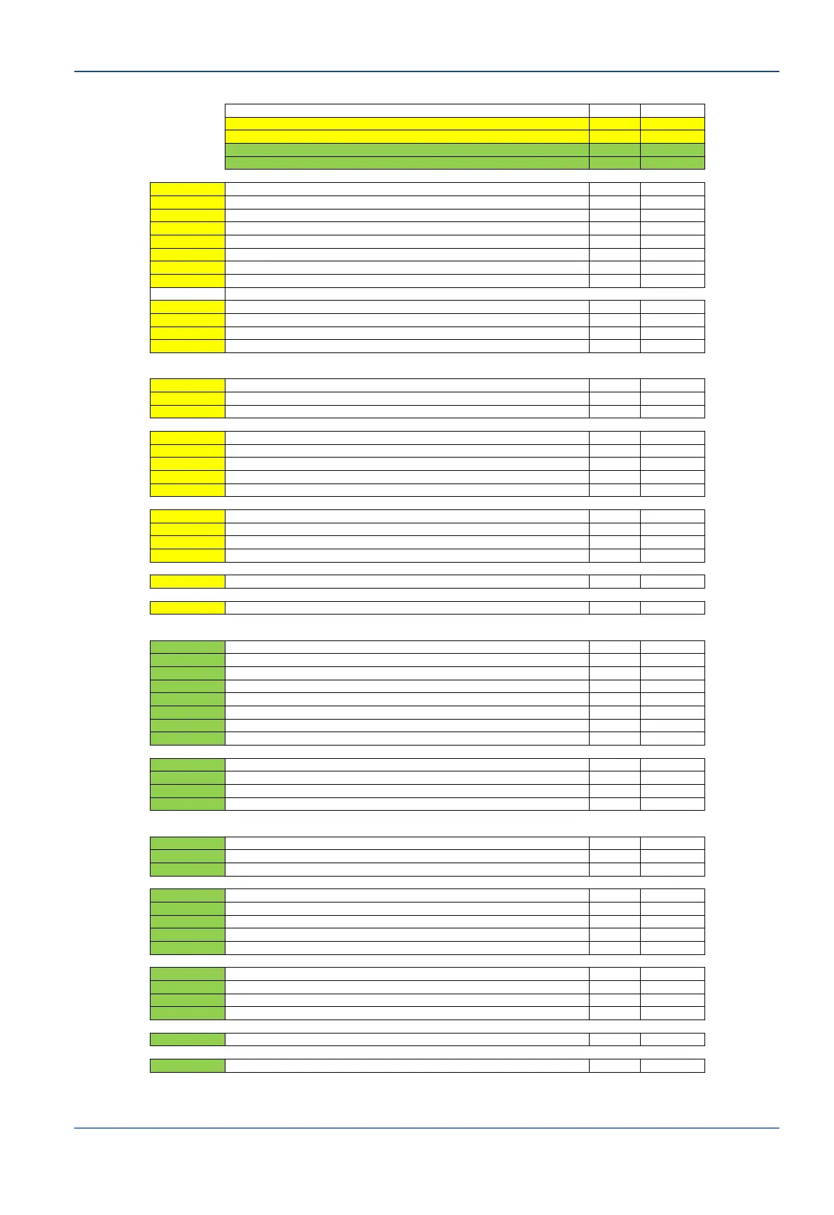
Parameter Unit Value
System Type 1 N/A OTRx4
System Band 1 N/A Ku
System Type 2 N/A OTRx4
System Band 2 N/A Ku
Transponder Saturation EIRP dBW 39.0
Output Backoff dB 4.0
Transponder Bandwidth MHz 36.0
Terminal Used Bandwidth (Rx) MHz 1.0
Downlink Frequency GHz 11.200
OrBand Antenna Gain (Typical) dBi 41.0
LNB Gain (Typical) dB 63.0
LNB Local oscillator MHz 10000
Derived Fractional Used Bandwidth dB -15.6
Derived Downlink Path Loss dB 204.5
dBW to dBm conversion factor dB 30.0
LNB Output Power dBm -51.1
POINT
G Derived LNB Output Power (D24), depends on Satellite EIRP, BW,Ant. Gain, etc, dBm -51.1
F to E, D to C Total Pedestal Attenuations: Cables (L-Band cables) + Rotary Joint + Splitter dB -14
C Derived Output Level Rx from Pedestal dBm -65.1
G Rx C-Band Frequency MHz 11200
Rx L Band Frequency, Depend on LNB LO (D19) MHz 1200
Which LMR Cable Type ? (400 or 600) 600
C to B ADE to BDE LMR Cable length Meter 50.0
C to B Derived Cable Attenuation (according to length and LMR Type 400 or 600) dB -4.8
CCU1U BDMx Tx Attenuation Selector (0dB or -8dB) dB 0
CCU1U ADMx/BDMx Total Gain (Rx path) dB 30.0
CCU1U Standard CCU Losses dB -1.0
DSS Standard Dual System Selector Switch Box Losses dB -0.2
F to A Derived Total ADE to BDE Gain/Loss (according to length) dB 10.0
A Derived L-Band (Rx) Input to Modem with Standard CCU dBm -41.1
Transponder Saturation EIRP dBW 39.0
Output Backoff dB 4.0
Transponder Bandwidth MHz 36.0
Terminal Used Bandwidth (Rx) MHz 1.0
Downlink Frequency GHz 11.200
OrBand Antenna Gain (Typical) dBi 41.0
LNB Gain (Typical) dB 63.0
LNB Local oscillator MHz 10000
Derived Fractional Used Bandwidth dB -15.6
Derived Downlink Path Loss dB 204.5
dBW to dBm conversion factor dB 30.0
LNB Output Power dBm -51.1
POINT
g Derived LNB Output Power (D59), depends on Satellite EIRP, BW,Ant. Gain, etc, dBm -51.1
f to e, d to c Total Pedestal Attenuations: Cables (L-Band cables) + Rotary Joint + Splitter dB -14
c Derived Output Level Rx from Pedestal dBm -65.1
g Rx C-Band Frequency MHz 11200
Rx L Band Frequency, Depend on LNB LO (D54) MHz 1200
Which LMR Cable Type ? (400 or 600) 600
c to b ADE to BDE LMR Cable length Meter 100.0
c to b Derived Cable Attenuation (according to length and LMR Type 400 or 600) dB -9.6
DSS BDMx Tx Attenuation Selector (0dB or -8dB) dB 0
DSS ADMx/BDMx Total Gain (Rx path) dB 30.0
DSS Standard CCU Losses dB -1.0
DSS Standard Dual System Selector Switch Box Losses dB -0.2
f to A Derived Total ADE to BDE Gain/Loss (according to length) dB 5.2
A Derived L-Band (Rx) Input to Modem with Standard CCU dBm -45.9