BDE Installation Procedure Installation Procedure
5-8 Ocean TRx™ 4500 Installation and Operations Manual
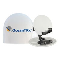
3. For CCU with 10MHz reference signal - connect the Modem as follows:
CCU AUX-IF2 port to CCU Tx port
CCU AUX-IF1 port Modem Tx port
CCU Rx port to Modem Rx port
Figure 5-8: CCU with 10 MHz Tx/Rx Modem Connections
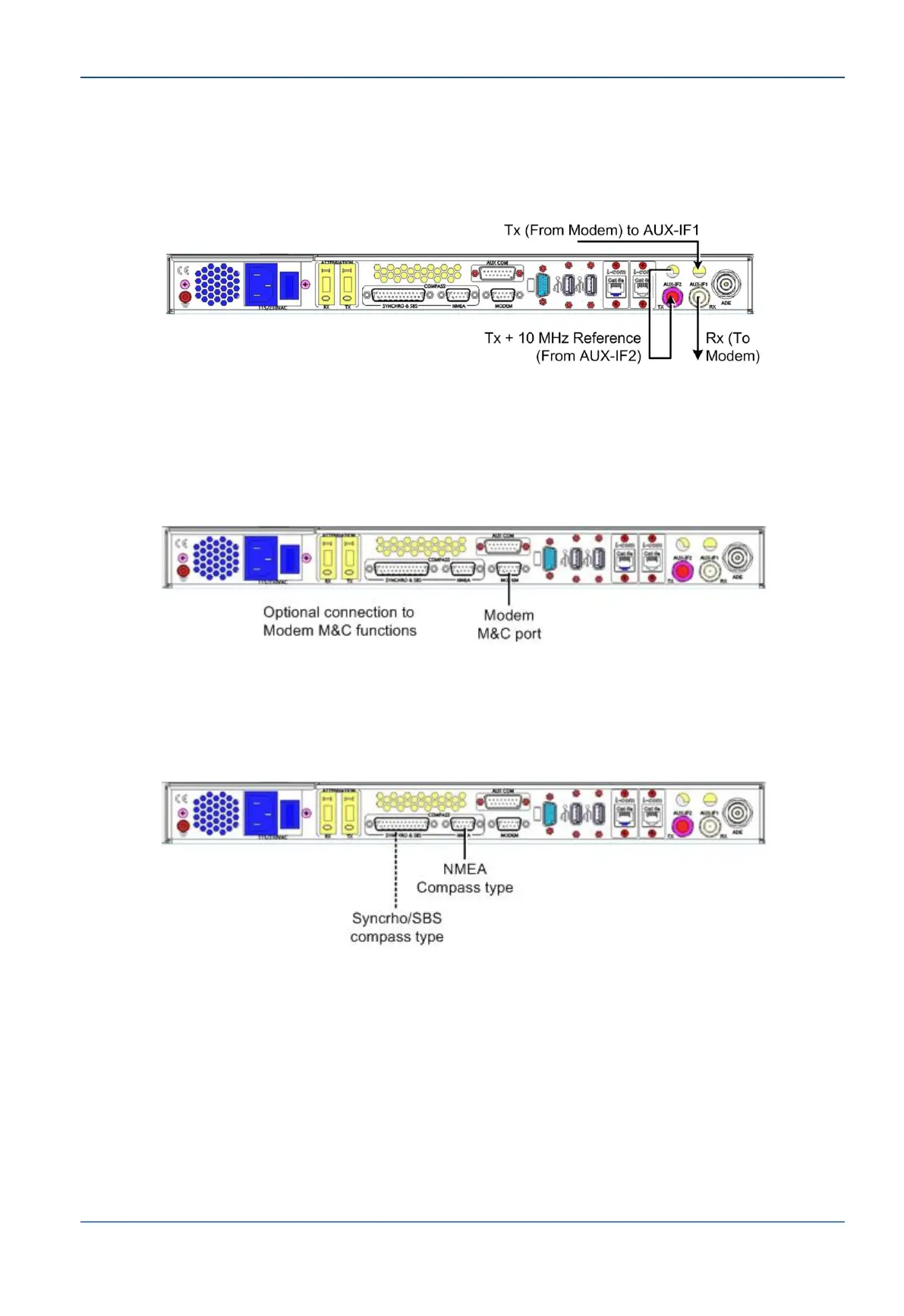
4. Modem M&C functionality - the CCU supports a number of modem M&C functions
including IRD lock, GPS output and modem monitor via the RS-232 9-pin MODEM
connector.
Optional - Connect CCU Modem port to Modem M&C port. Use RS-232 cable.
Figure 5-9: Connection to Modem M&C Function
5. Compass connections - the CCU Supports SYNCHRO, SBS and NMEA Compasses.
Connect your compass to the relevant connector as show below.
Figure 5-10: Compass Connections