10
• Install all other OutBack components rst.
• Run the CAT 5 cable from the source (HUB, FX or Charge Controller) to the MATE’s
location. Connect the CAT5 cable to the source but not to the MATE just yet.
• If connecting a computer to the MATE or MATE2, run a serial cable from the computer to
the MATE’s location, but do not connect the cable at this time.
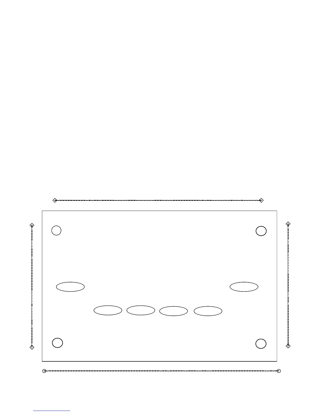
• Unsnap the MATE’s back plate and nd the four screw holes. If a MATE2 version is used,
the back cover need not be removed.
• e MATE and MATE2 are designed for easy wall mounting using appropriate fasteners
(molly bolts, screws, etc.).
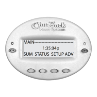
• Power up every OutBack device connected directly or indirectly (through the HUB) to the
MATE and then connect the CAT5 cable to the jack and, if used, the computer serial cable
to the RS-232 port, on the back MATE or MATE2.
• If installing the MATE, snap the MATE onto the back plate and push any excess cable back
into the wall. If installing the MATE2 version, secure its four corners to the wall.