Issue: 1.2-17-2 Ovation Systems Ltd Page 10
www.ovation.co.uk
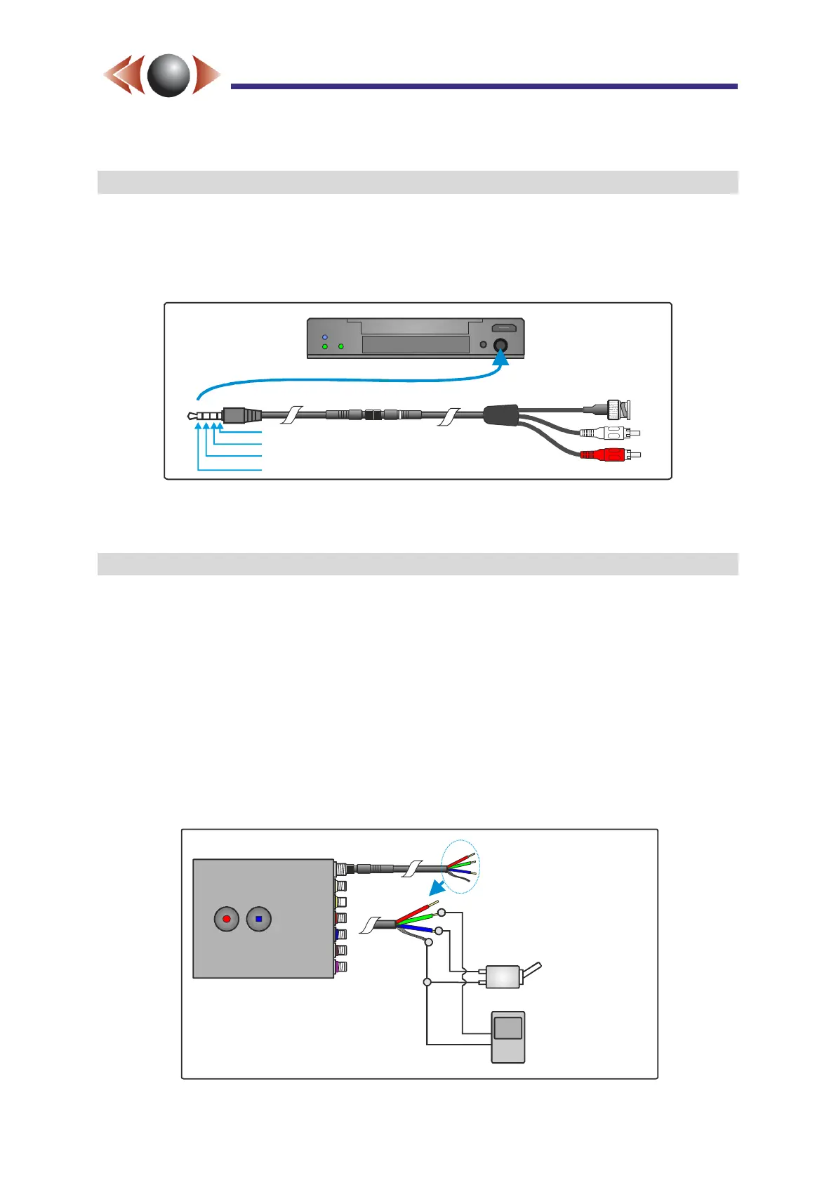
2.8 Audio & Video Monitor Output
The front panel 4-way jack socket is an analogue video and audio monitor of the input feeds.
The video output includes the on-screen text overlay and the audio is after any microphone
gain. Any HD inputs are down-scaled to SD and, when more than 1 SD inputs are enabled,
this output is shown as a quad with an update of approximately 5 frames per second.
Figure 11: Audio & Video Monitor Output Jack
TIP► Standard headphones with a 3.5m jack can be used to monitor the audio.
2.9 External Control Inputs (Record Switches and Triggers)
Recording can be controlled in a number of different ways:
The start / stop buttons on the unit;
The external switches / triggers (see below);
Internal triggers such as motion detection, GPS movement, and timers.
The DC input connector to FlashBack-4 also includes two external control inputs; “Record
Control 1” (Blue wire) and “Record Control 2” (Green wire).
By default “Record Control 1” is configured to record when connected to ground (eg for use
with a record switch) and “Record Control 2” records for a minimum pre-set time (default 10
seconds) when connected to ground (eg for use with a trigger device such as a PIR
detector). Figure 12 below shows an example of how the external trigger inputs are used.
Figure 12: Example External Record Switches and Triggers
A/V monitor out
A/V out 4 pole jack
Audio Left Out
Audio Right Out
Ground
Video Out
Record Control 1
()Record Switch
Record Control 2
()Record Trigger
Red - DC in
Green - Control 2 (Trigger In)
Blue - Control 1 (Rec Switch)
Braid - Ground